Question 9.2.2: A toggle clamp holds workpiece F (Figure 1) (a) Assuming the...
ANALYSIS OF A TOGGLE CLAMP
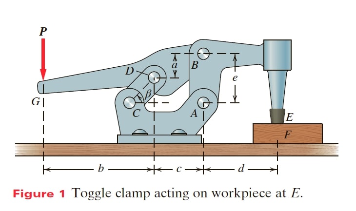
A toggle clamp holds workpiece F (Figure 1)
(a) Assuming the weight of the clamp members can be ignored, determine the mechanical advantage of this toggle clamp, defined as the ratio of the output force at the workpiece to P.
(b) For the dimensions shown in the accompanying list, what is the mechanical advantage of this toggle clamp?
| Dimensions for Toggle Clamp a = 1 in. b = 4.5 in. c = 1.5 in. d = 4 in. e = 3 in. β is such that cos β = 4/5, sinβ= 3/5 |
Learn more on how we answer questions.
Goal Find the force at E (F_{E}) in terms of P, expressed as mechanical advantage. Also calculate the mechanical advantage for a particular geometry.
Given The configuration of the toggle clamp and its key dimensions.
Assume The system is planar, the pin connections A, B, C, D are all frictionless, the clamping force at E is purely vertical, as is the input force P. member CD is a two-force member (because it has pin connections at its ends and is loaded by force through its ends).
Draw We draw free-body diagrams of individual parts of the toggle clamp, recognizing that F_{D} is at angle β with the horizontal because member CD is a two-force member (Figure 2 and Figure 3).
Formulate Equations and Solve (a) We first isolate the handle (Figure 2); doing this allows us to relate F_{B} to P. Next we isolate member ABE (Figure 3); doing this allows us to relate F_{B} to F_{E} . Finally, we relate F_{E} to P. We can write F_{D}= F_{Dx} i+ F_{Dy}j . Furthermore, because member CD is a two-force member, we can write F_{Dx}=\left\|F_{D}\right\| \cos \beta and F_{Dy}=\left\|F_{D}\right\| \sin \beta .Now we formulate the equilibrium equations for the planar system in Figure 2.
\sum{M_{z @ B} }\left(\curvearrowleft + \right) =P\left(b+ c\right) – \left\|F_{D}\right\| \sin \beta \left(c\right) + \left\|F_{D}\right\| \cos \beta\left(a\right) = 0
\left\|F_{D}\right\|=\frac{b+ c}{c\sin \beta – a\cos \beta } (1)
\sum{F_{x} \left(\rightarrow + \right) } = – F_{Bx}+ \left\|F_{D}\right\| \cos \beta =0\Rightarrow F_{Bx}=\left\|F_{D}\right\| \cos \beta (2)
\sum{F_{y}\left(\uparrow + \right) } =- F_{By}+ \left\|F_{D}\right\| \sin \beta- P=0\Rightarrow F_{By}= \left\|F_{D}\right\| \sin \beta- P (3)
We substitute (1) into (2) and (3) to express the force components at B in terms of the input force P:
From (2) F_{Bx}=\frac{\left(b+ c\right) \cos \beta }{c\sin \beta – a\cos \beta } P (2*)
From (3) F_{By}=\left\lgroup\frac{\left(b+ c\right) \sin \beta }{c\sin \beta – a\cos \beta } -1\right\rgroup P (3*)
moment equilibrium for member ABE (Figure 3) gives:
\sum{M_{z @ A} }\left(\curvearrowleft + \right) =- F_{Bx}e+F_{E}d=0
F_{E}=\frac{e}{d}F_{Bx}\underbrace{\Rightarrow }_{substituting from (2*)} F_{E}=\left\lgroup\frac{e}{d}\right\rgroup \frac{\left(b+ c\right) \cos \beta }{c\sin \beta – a\cos \beta } P (4)
Rearranging (4) gives us the ratio we are interested in:
\frac{F_{E}}{P } \left\lgroup\frac{e}{d}\right\rgroup \frac{\left(b+ c\right) \cos \beta }{c\sin \beta – a\cos \beta }
We are asked to calculate the ratio for the particular geometry given. Substituting the values of a, b, c, d and e we find that
The mechanical advantage of the toggle clamp is 36 to 1.
Check To check our result, we consider a free-body diagram of the whole toggle clamp, as shown in Figure 4, with calculated force values (based on the dimensions given) shown. Notice that F_{Dx} and F_{Ax} balance one another. In addition, if we sum the moments around point A we find:
\sum{M_{z @ A} }\left(\curvearrowleft + \right) =P(6 in.) – 36 P(1.5 in.) + 48 P(2 in.) + 36 P(4 in.) = 0
Therefore our calculated values show that the toggle clamp as a whole is in equilibrium.


