Question 8.5: Analysis of a Cam-Follower Arm Problem: A beam is supported ...
Analysis of a Cam-Follower Arm
Problem: A beam is supported on two pins in bearings having small clearance. Estimate its maximum deflection and spring rate at the load point.
Given: The beam dimensions in Figure 8-23 are: a = 8, l = 20, b = 0.75, h = 2, d = 0.5 in, e = 0.375 in, f = 0.438 in, and g = 0.375 in. The pin holes are all 0.5-in-dia. The load F = 100 lb. The beam and pins are steel and the bearings are bronze on steel. The beam cross section is tapered and pocketed to reduce its mass. The basic geometry is as in Example 8-4.
Assumptions: Loading and support reactions are parallel but out of plane. Pin supports are significantly stiffer than the beam.

Learn more on how we answer questions.
1 Example 8-4 analyzed a simplified version of this beam in which the loads and reactions were all assumed to be coplanar and the beam cross section geometry was constant over the length of the beam rather than tapered and pocketed as shown in Figure 8-23. These simplifications allowed a closed form solution to be done using beam theory in order to compare it to the 2-D FEA results. This is an important step in any FEA analysis because it provides a check on the validity of your choices of mesh size and boundary conditions. Once those issues have been resolved, you will be ready to analyze the more complicated geometry of the real part with some confidence that the results will be valid.
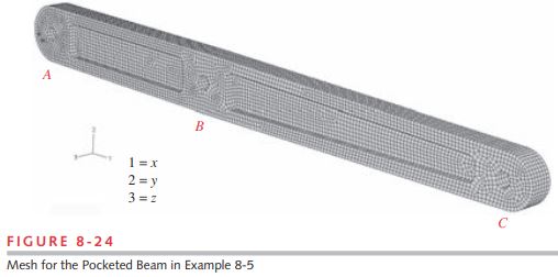
2 Figure 8-24 shows a mesh of 3-D, 8-node linear hexahedral elements (bricks) applied to the tapered, pocketed beam of Figure 8-23. Since we are primarily interested in deflections in this example, mesh refinement is not as critical as it is when accurate stress estimates are also needed.
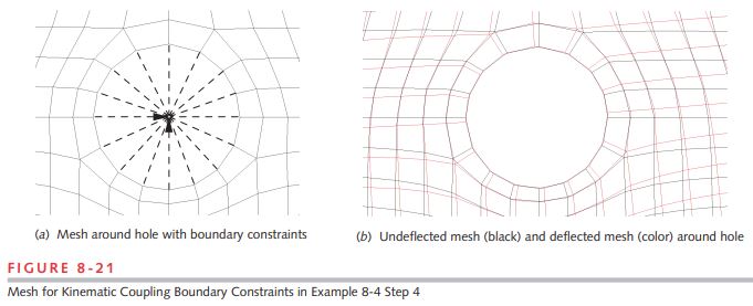
3 Because the applied and reaction loads on this part are not in the central plane of the beam, but are offset to either side in the z-direction, the boundary conditions and load must be applied to nodes placed at those locations. Figure 8-25 shows these boundary conditions with rigid-element “kinematic constraints” connecting a node offset the proper distance at the center of the “pin” to nodes on the physical beam. This is the same technique as was used in step 4 of Example 8-4 (see Figure 8-21, p. 501), but note that the z-offset makes these connections form a set of rigid element “cones” that attach the single node at the boundary condition (or load) to all the nodes on the inside of its pin hole. This technique effectively creates a rigid “pin” in the form of the offset node connected rigidly to the pin hole and allows the part to rotate about the z-axis of the pin.
4 Constraints are applied at A to fix displacement in x, y, and z, and to fix rotation about x and y. Displacement at B is fixed in y. The x and z displacements at B are left unconstrained because the roller on the cam allows motion in those directions. The 100-lb load is applied in the positive y direction at C. See Figure 8-25.
5 Figure 8-26 shows the deflection (exaggerated by 10x) and the von Mises stress distribution in the beam. Stress values are not shown as the mesh was not refined to give accurate results. The stress contour plots serve to show the “hot spots” of stress in this case. If this estimate of stress had indicated any dangerously high levels (which it did not), then additional runs of the model with finer meshes would have been done. Note, however, that the beam shows significant torsional as well as bending deflection because of the offset loads. This should not be surprising given its out-of-plane loading. The deflection in the y-direction at the applied load (at C) is 0.0193 in.
6 The deflection calculated by the 2-D model of the same beam with simplified geometry and coplanar loads was 0.0066 in, about 1/3 of the above value. One should expect this 3-D model to have larger deflection since the beam has been weakened by its taper and removal of the pocket material (to reduce mass for better dynamics), and because the offset loads superpose a torsional deflection on that due to bending. Remember that the simpler model of this beam used in Example 8-4 was created for the purpose of determining the most appropriate set of boundary conditions. For that, we needed a model simple enough to check with a closed-form method. That done, we could proceed to this more complex model and have some confidence in its result.
7 In this case (which was a real cam-follower arm) the deflection of 0.0193 in (0.5 mm) was deemed too large. Thus some redesign was needed. Since the torsional deflection was of the same order as the bending deflection, the beam model was redesigned with the pockets removed to increase its torsional stiffness.* The mesh for this redesigned arm is shown in Figure 8-27. The boundary constraints and load were applied in the same way as in step 4 and Figure 8-25.
8 Figure 8-28 shows the deflection (exaggerated by 10x) and the von Mises stress distribution in the redesigned beam. The deflection at the load is now 0.0099 in, about half that of the pocketed beam design. This was deemed to be acceptable.
9 The spring rate for the beam in bending is easily calculated from the bending deflection and applied force as k = F / y = 100 / 0.0099 = 10 101 lb/in.
* Refer to Example 4-8 (p. 175) to review why open sections such as the I-beam shape of this pocketed beam are a poor choice for torsional loading situations.