Question 5.12: Analysis of a Wye–Wye System A balanced positive-sequence wy...
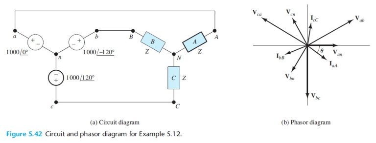
Analysis of a Wye–Wye System A balanced positive-sequence wye-connected 60-Hz three-phase source has line-to-neutral voltages of VY = 1000 V. This source is connected to a balanced wye-connected load. Each phase of the load consists of a 0.1-H inductance in series with a 50-Ω resistance. Find the line currents, the line-to-line voltages, the power, and the reactive power delivered to the load. Draw a phasor diagram showing the line-to-neutral voltages, the line-to-line voltages, and the line currents. Assume that the phase angle of Van is zero.
Learn more on how we answer questions.
Solution First, by computing the complex impedance of each phase of the load, we find that
Z=R+j\omega L=50+j2\pi(60)(0.1)=50+j37=62.62\angle 37.02^\circ
Next, we draw the circuit as shown in Figure 5.42(a). In balanced wye–wye calculations, we can assume that n and N are connected. (The currents and voltages are the same whether or not the neutral connection actually exists.) Thus, Van appears across phase A of the load, and we can write
\mathrm{I}_{aA}=\frac{\mathrm{V}_{an}}{Z}=\frac{1000\angle 0^\circ}{62.62\angle 37.02^\circ}=15.97\angle -37.02^\circ
Similarly,
\mathrm{I}_{bB}=\frac{\mathrm{V}_{bn}}{Z}=\frac{1000\angle -120^\circ}{62.62\angle 37.02^\circ}=15.97\angle -157.02^\circ
\mathrm{I}_{cC}=\frac{\mathrm{V}_{cn}}{Z}=\frac{1000\angle 120^\circ}{62.62\angle 37.02^\circ}=15.97\angle 82.98^\circ
We use Equations 5.103, 5.104, and 5.105 to find the line-to-line phasors:
\mathrm{V}_{ab}=\mathrm{V}_{an}\times \sqrt{3}\angle 30^\circ=1732\angle 30^\circ
\mathrm{V}_{bc}=\mathrm{V}_{bn}\times \sqrt{3}\angle 30^\circ=1732\angle -90^\circ
\mathrm{V}_{ca}=\mathrm{V}_{cn}\times \sqrt{3}\angle 30^\circ=1732\angle 150^\circ
The power delivered to the load is given by Equation 5.94:
p(t)=3\frac{V_YI_L}{2}\cos{(\theta)}=3 \left(\frac{1000\times 15.97}{2} \right) \cos{(37.02^\circ)}=19.13\mathrm{~kW}
The reactive power is given by Equation 5.98:
Q=3\frac{V_YI_L}{2}\sin{(\theta)}=3V_{Y\mathrm{rms}}I_{L\mathrm{rms}}\sin{(\theta)} (5.98)
Q=3\frac{V_YI_L}{2}\sin{(\theta)} =3 \left(\frac{1000\times 15.97}{2} \right) \sin{(37.02^\circ)}=14.42\mathrm{~kVAR}
The phasor diagram is shown in Figure 5.42(b). As usual, we have chosen a different scale for the currents than for the voltages.