Question 8.2: Boundary Conditions of a Sliding Beam Problem: A rectangular...
Boundary Conditions of a Sliding Beam
Problem: A rectangular cross-section sliding beam is supported in sliding bearings and loaded in bending by a transverse force at a fixed location in x as shown in Figure 8-11a. Determine a reasonable boundary condition arrangement and compare its prediction of deflection with closed form solutions.
Given: The beam dimensions are shown in Figure 8-11a. The load F = 250 lb. The material is steel.
Assumptions: The supporting bearings are considered to be much stiffer than the beam. Beam weight is negligible compared to the applied load. The bearings have 0.001-inch clearance around the beam cross section to allow sliding.

Learn more on how we answer questions.
1 The deflection curves from closed-form solutions for the cases in Figures 8-11b and c are shown in Figure 8-12. The maximum deflection for the fixed-fixed model is –0.00036 in and is –0.00090 in for the simply supported model. The end fixation reduces total deflection by a factor of 3. This is because the moment constraints make the beam slope zero at the bearings and effectively stiffen it.
2 Even though this is a 3-D system, we will first use a 2-D plane-stress FEA model with quad elements for simplicity. Because FEA is displacement based, the model’s deflections provide a good means to check whether the constraints applied are reasonable. If the deflections are believable and the mesh convergence is separately proven, then one can have some confidence in the results. For this example, the load is applied in the center of the span.
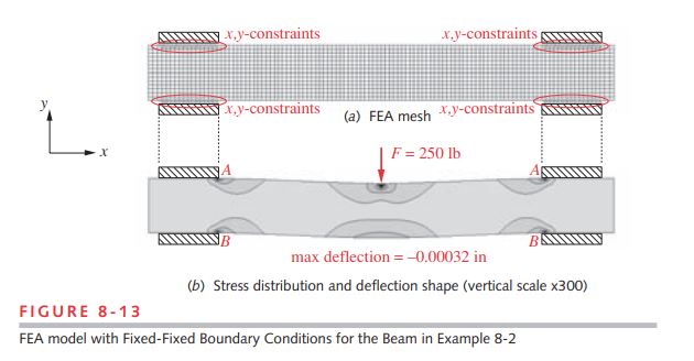
3 Figure 8-13a shows the mesh for the fixed-fixed case with the nodes of all the elements that contact the bearings constrained in the x – and y -directions to simulate moment joints at each bearing. Figure 8-13b shows the deflected shape and the
maximum deflection as found by FEA, which is –0.00032 in, close to the value found in step 1. Note the stress concentrations at the point of force application and at points A and B where the edges of the bearings contact the slide. This shows the effect of boundary conditions on local stresses.
4 Figure 8-14a shows the same meshed model as Figure 8-13a but the boundary conditions have been changed to simulate simple support at each end. At the left end (circled at point A) a single node at the inner edge of the bearing is fixed in x and y to represent a hinge. At the right end (circled at point B) a single node at the inner edge of the bearing is constrained only in y to represent the roller support. Figure 8-14b shows the deflected shape and the maximum deflection of the simply supported beam as found by FEA, which is –0.00099 in, close to the value found in step 1. Note the stress concentrations at the point of force application and at points A^{\prime} and B^{\prime} where the edges of the bearings contact the slide, showing the effect of boundary conditions on local stresses. Note also that the top edges of the beam do not contact the insides of the upper bearings, consistent with the closed-form calculation. (See Figure 8-12.)