Question 2.2: Circuit Analysis Using Series/Parallel Equivalents Find the ...
Circuit Analysis Using Series/Parallel Equivalents
Find the current, voltage, and power for each element of the circuit shown in Figure 2.5(a).

Learn more on how we answer questions.
First, we combine resistances in series and parallel. For example, in the original circuit, R_2 and R_3 are in parallel. Replacing R_2 and R_3 by their parallel equivalent, we obtain the circuit shown in Figure 2.5(b). Next, we see that R_1 and R_{eq1} are in series. Replacing these resistances by their sum, we obtain the circuit shown in Figure 2.5(c).
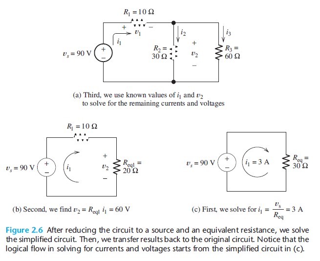
After we have reduced a network to an equivalent resistance connected across the source, we solve the simplified network. Then, we transfer results back through the chain of equivalent circuits. We illustrate this process in Figure 2.6. (Figure 2.6 is identical to Figure 2.5, except for the currents and voltages shown in Figure 2.6.
Usually, in solving a network by this technique, we first draw the chain of equivalent networks and then write results on the same drawings. However, this might be confusing in our first example.)
First, we solve the simplified network shown in Figure 2.6(c). Because R_{eq} is parallel with the 90-V voltage source, the voltage across R_{eq} must be 90 V, with its positive polarity at the top end. Thus, the current owing through R_{eq} is given by
i_1=\frac{v_s}{R_{eq}} =\frac{90\mathrm{~V}}{30~\Omega} =3\mathrm{~A}
We know that this current flows downward (from plus to minus) through R_{eq}. Since v_s and R_{eq} are in series in Figure 2.6(c), the current must also flow upward through v_s. Thus,i_1=3\mathrm{~A} flows clockwise around the circuit, as shown in Figure 2.6(c).
Because R_{eq} is the equivalent resistance seen by the source in all three parts of Figure 2.6, the current through v_s must be i_1=3\mathrm{~A}, flowing upward in all three equivalent circuits. In Figure 2.6(b), we see that i_1 flows clockwise through v_s,R_1, and R_{eq1}. The voltage across R_{eq1} is given by
v_2=R_{qe1}i_1=20~\Omega\times 3\mathrm{~A}=60\mathrm{~V}
Because R_{eq1} is the equivalent resistance for the parallel combination of R_{2} and R_{3}, the voltage v_{2} also appears across R_{2} and R_{3} in the original network.
At this point, we have found that the current through v_s and R_{1} is i_1=3\mathrm{~A}. Furthermore, the voltage across R_{2} and R_{3} is 60 V. This information is shown in Figure 2.6(a). Now, we can compute the remaining values desired:
i_2=\frac{v_2}{R_2}=\frac{60\mathrm{~V}}{30~\Omega} =2\mathrm{~A}
i_3=\frac{v_2}{R_3}=\frac{60\mathrm{~V}}{60~\Omega} =1\mathrm{~A}
(As a check, we can use KCL to verify that i_1=i_2+i_3.)
Next, we can use Ohm s law to compute the value of v_1:
v_1=R_1i_1=10~\Omega\times 3\mathrm{~A}=30\mathrm{~V}
(As a check, we use KVL to verify that v_s=v_1+v_2.)
Now, we compute the power for each element. For the voltage source, we have
p_s=-v_si_1
We have included the minus sign because the references for v_s and i_1 are opposite to the passive configuration. Substituting values, we have
p_s=-\left(90\mathrm{~V}\right) \times 3\mathrm{~A}=-270\mathrm{~W}
Because the power for the source is negative, we know that the source is supplying energy to the other elements in the circuit.
The powers for the resistances are
p_1=R_1i_1^2=10~\Omega\times \left(3\mathrm{~A}\right)^2=90\mathrm{~W}
p_2=\frac{v_2^2}{R_2}=\frac{\left(60\mathrm{~V}\right)^2 }{30~\Omega}=120\mathrm{~W}
p_3=\frac{v_2^2}{R_3}=\frac{\left(60\mathrm{~V}\right)^2 }{60~\Omega}=60\mathrm{~W}
(As a check, we verify that p_s+p_1+p_2+p_3=0, showing that power is conserved.)