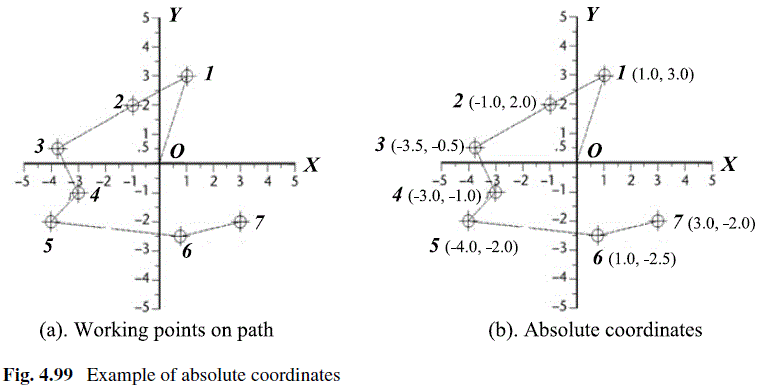
Question 4.7: Determine the absolute coordinates of working points shown i...
Determine the absolute coordinates of working points shown in Fig. 4.99a.

Learn more on how we answer questions.
The absolute coordinates are measured from origin O; therefore, the coordinates of the working points (1, 2, …, 7) in Fig. 4.99a are determined as (1.0, 3.0), (-1.0, 2.0), (-3.5, -0.5), (-3.0, – 1.0), (-4.0, -2.0), (1.0, -2.5), and (3.0, -2.0) in Fig. 4.99b, respectively.
Absolute coordinates also apply to the default two-axis coordinate system for a CNC lathe. For a lathe, absolute coordinates take the reference from origin (X0, Z0) as shown in Fig. 4.100a. To find Z- and X-coordinates of a working point, project the working point on Z-axis and X-axis, respectively. The absolute coordinates of the working points P_{1} to P_{6} are determined in Fig. 4.100b. Note that the X-coordinates can be either radical (X_{R} ) or diametric (X_{D} ).
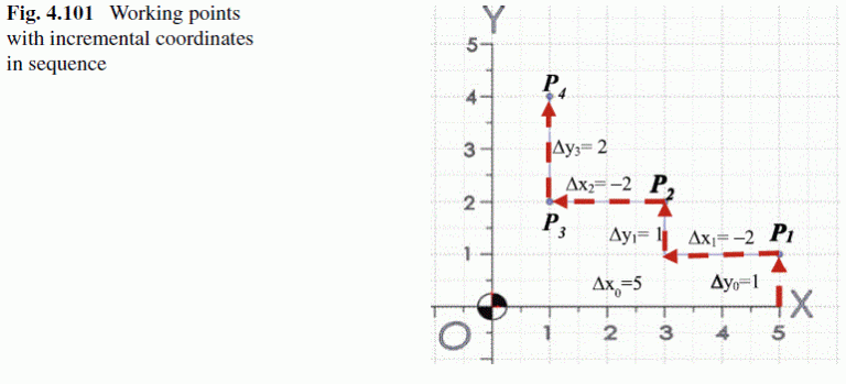
Incremental coordinates are measured from existing points. A new working point can be defined by specifying a relative distance of an existing point. Figure 4.101 shows an example of defining incremental coordinates for working points in a toolpath.

