Question 7.9: Determine the deflection at point C of the beam shown in Fig...
Determine the deflection at point C of the beam shown in Fig. 7.14(a) by the virtual work method.

Learn more on how we answer questions.
This beam was previously analyzed by the moment-area and the conjugate-beam methods in Examples 6.7 and 6.13, respectively.
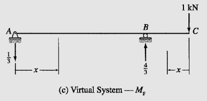
The real and virtual systems for this problem are shown in Fig. 7.14(b) and (c), respectively. The real and virtual loadings are discontinuous at point B, so the beam is divided into two segments, AB and BC. The x coordinates used for determining the bending moment equations are shown in Fig. 7.14(b) and (c), and the equations for M and M_v obtained for each of the two segments of the beam are tabulated in Table 7.7. The deflection at C can now be determined by applying the virtual work expression given by Eq. (7.30), as follows:
1(Δ) = \int_{0}^{L}{\frac{M_vM}{EI} dx} (7.30)
| TABLE 7.7 | ||||
| Segment | x Coordinate | M (kN-m) | M_v (kN-m) | |
| Origin | Limits(m) | |||
| AB | A | 0-9 | 115x – x² | –\frac{x}{3} |
| CB | C | 0-3 | -60x | -x |
1(Δ_C) = \frac{1}{EI}[\int_{0}^{9}{(-\frac{x}{3})(115x – x^2) dx} + \int_{0}^{9}{(-x)(-60x) dx} ]
(1 kN)Δ_C = -\frac{8228.75 kN^2-m^3}{EI}
Therefore,
Δ_C = -\frac{8228.75 kN^2-m^3}{EI} = -\frac{8228.75}{200(10^6)800(10^{-6})} = -0.0514 mΔ_C = 51.4 mm ↑