Degrees of Freedom From the analytical model of the frame shown in Fig. 18.13(b), we observe that while joints 1 and 3 of the structure can neither translate nor rotate, joint 2 is free to translate as well as rotate. Thus the frame has three degrees of freedom: the translations d_1 and d_2 in the X and Y directions, respectively, and the rotation d_3 of joint 2.
Structure Stiffness Matrix
Member 1 Since the local xy coordinate system for this member coincides with the global XY coordinate system, no coordinate transformations are needed; that is, the member stiffness relations in the local and global coordinates are the same. By substituting E = 201.4 kPa, I = 0.039 m^4, A = 1111 cm², and L = 30 m into Eq. (18.5), we obtain
k =\frac{E I}{L^{3}}\left[\begin{array}{cccccc}\frac{A L^{2}}{I} & 0 & 0 & -\frac{A L^{2}}{I} & 0 & 0 \\0 & 12 & 6 L & 0 & -12 & 6 L \\0 & 6 L & 4 L^{2} & 0 & -6 L & 2 L^{2} \\-\frac{A L^{2}}{I} & 0 & 0 & \frac{A L^{2}}{I} & 0 & 0 \\0 & -12 & -6 L & 0 & 12 & -6 L \\0 & 6 L & 2 L^{2} & 0 & -6 L & 4 L^{2}\end{array}\right] (18.5)
 (1)
(1)
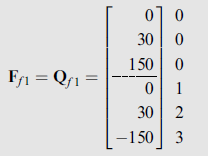
By using the fixed-end moment expressions given inside the back cover of the book, we evaluate the fixed-end moments due to the 2-kN/m load as
Q_{f 3} = -Q_{f 6} = \frac{2(30)^2}{12} = 150 kN-mBy applying equilibrium equations to the free body of the member, we obtain (Fig. 18.13(c))
Q_{f 2} = Q_{f 5} = 30 kNThus,
 (2)
(2)
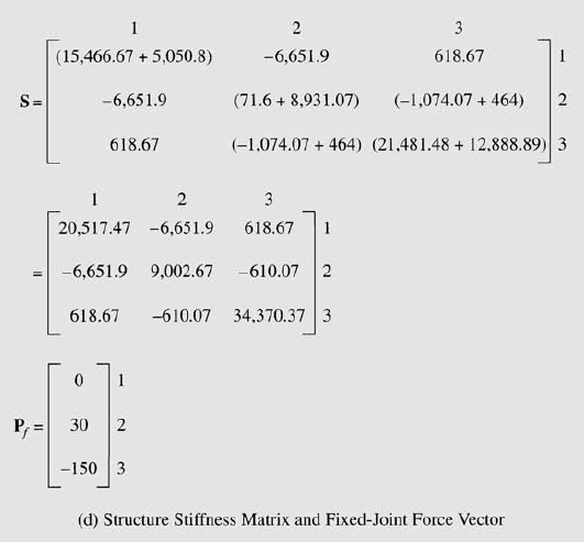
By using the structure degree of freedom numbers, 0, 0, 0, 1, 2, 3, for this member, the pertinent elements of K_1 and F_{f 1} are stored in their proper positions in the structure stiffness matrix S and the fixed-joint force vector P_f , respectively, as shown in Fig. 18.13(d).
Member 2 By substituting E = 201.4 kPa, I = 0.019 m^4, A = 833 cm², and L = 25 m into Eq. (18.5), we obtain
k_2 =\begin{bmatrix} 13,920 & 0 & 0 &-13,920 &0 &0 \\ 0 & 61.87 & 773.33 &0 &-61.87 &773.33\\ 0 & 773.33 & 12,888.89 &0 &-773.33 &6,444.44\\-13,920 & 0 & 0 & 13,920 & 0 & 0 \\ 0 & -61.87 & -773.33 & 0 & 61.87 & -773.33\\ 0 & 773.33 & 6,444.44 & 0 & -773.33 & 12,888.89 \end{bmatrix} (3)
Since member 2 is not subjected to any external loads,
Q_{f 2} = 0 (4)
By using the global coordinates of the beginning joint 3 and the end joint 2, we determine the direction cosines of member 2 as (Eq. (18.13))
\cos \theta=\frac{X_{e}-X_{b}}{L}=\frac{X_{e}-X_{b}}{\sqrt{\left(X_{e}-X_{b}\right)^{2}+\left(Y_{e}-Y_{b}\right)^{2}}} (18.13a)
\sin \theta=\frac{Y_{e}-Y_{b}}{L}=\frac{Y_{e}-Y_{b}}{\sqrt{\left(X_{e}-X_{b}\right)^{2}+\left(Y_{e}-Y_{b}\right)^{2}}} (18.13b)
\cos θ =\frac{X_2 – X_3}{L} = \frac{30 – 45}{25} = -0.6\sin θ =\frac{Y_2 – Y_3}{L} = \frac{0 – (-20)}{25} = 0.8
Substitution of these values into Eq. (18.12) yields the following transformation matrix for the member:
T =\left[\begin{array}{cccccc}\cos \theta & \sin \theta & 0 & 0 & 0 & 0 \\-\sin \theta & \cos \theta & 0 & 0 & 0 & 0 \\0 & 0 & 1 & 0 & 0 & 0 \\0 & 0 & 0 & \cos \theta & \sin \theta & 0 \\0 & 0 & 0 & -\sin \theta & \cos \theta & 0 \\0 & 0 & 0 & 0 & 0 & 1\end{array}\right] (18.12)
T_2 =\begin{bmatrix} -0.6 & 0.8 & 0 &0 &0 &0 \\ -0.8 & -0.6 & 0 &0 &0 &0\\ 0 & 0 & 1 &0 &0 &0\\0 & 0 & 0 & -0.6 & 0.8 & 0 \\ 0 & 0 & 0 & -0.8 & -0.6 & 0\\ 0 & 0 & 0 & 0 & 0 & 1 \end{bmatrix} (5)
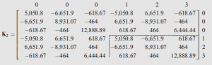
To determine the member stiffness matrix in global coordinates, K_2, we substitute the matrices k_2 and T_2 into the relationship K = T^T kT (Eq. (18.26)) and carry out the necessary matrix multiplications to obtain
K = T^T kT (18.26)
 (6)
(6)
Note that K_2 is symmetric. By using the structure degree of freedom numbers, 0, 0, 0, 1, 2, 3, for member 2, the relevant elements of K_2 are added into their positions in the S matrix, as shown in Fig. 18.13(d). Note that F_{f 2} = 0.
Joint Load Vector By comparing Fig. 18.13(a) and (b), we write
P = \begin{bmatrix} 0 \\ 0\\75 \end{bmatrix}Joint Displacements The stiffness relations for the entire frame, P – P_f = Sd, are written in expanded form as
\begin{bmatrix} 0 \\ 0\\75 \end{bmatrix} – \begin{bmatrix} 0 \\ 30\\-150 \end{bmatrix} = \begin{bmatrix} 20,517.47 & -6,651.9 &618.67\\ -6,651.9 & 9,002.67 & -610.07\\618.67 & -610.07 &34,370.37 \end{bmatrix} \begin{bmatrix} d_1 \\ d_2\\d_3 \end{bmatrix}or
\begin{bmatrix} 0 \\ -30\\225 \end{bmatrix} = \begin{bmatrix} 20,517.47 & -6,651.9 &618.67\\ -6,651.9 & 9,002.67 & -610.07\\618.67 & -610.07 &34,370.37 \end{bmatrix} \begin{bmatrix} d_1 \\ d_2\\d_3 \end{bmatrix}By solving these equations simultaneously, we determine the joint displacements to be
d = \begin{bmatrix} -0.00149 m \\ -0.00399 m\\0.0065 rad \end{bmatrix}Member End Displacements and End Forces
Member 1
u_1 = v_1 = \begin{bmatrix} v_1 \\v_2\\v_3 \\ v_4 \\ v_5 \\ v_6 \end{bmatrix} \begin{matrix} 0 \\0\\0 \\ 1 \\ 2 \\ 3 \end{matrix} = \begin{bmatrix} 0 \\0\\0 \\ d_1 \\ d_2 \\ d_3 \end{bmatrix} = \begin{bmatrix} 0 \\0\\0 \\ -0.00149 m \\ -0.00399 m \\ 0.0065 rad \end{bmatrix}By substituting k_1,Q_{f 1}, and u1 in the member stiffness relationship Q = ku + Q_f (Eq. (18.4)), we determine the member end forces to be
Q = ku + Q_f (18.4)
F_1 = Q_1 =\left[\begin{array}{c}23.05 kN \\37.27 kN \\224.1 kN – m \\ -23.05 kN \\22.73 kN \\-6.08 kN – m\end{array}\right]Member 2
v_2 = \begin{bmatrix} v_1 \\v_2\\v_3 \\ v_4 \\ v_5 \\ v_6 \end{bmatrix} \begin{matrix} 0 \\0\\0 \\ 1 \\ 2 \\ 3 \end{matrix} = \begin{bmatrix} 0 \\0\\0 \\ d_1 \\ d_2 \\ d_3 \end{bmatrix} = \begin{bmatrix} 0 \\0\\0 \\ -0.00149 m \\ -0.00399 m \\ 0.0065 rad \end{bmatrix}By substituting K_2, v_2, and F_{f 2} = 0 into the member stiffness relationship in global coordinates, F = Kv + F_f (Eq.(18.25)), we determine the member end forces in global coordinates to be
F _{2}=\left[\begin{array}{c}-23.04 kN \\22.71 kN \\39.12 kN – m \\23.04 kN \\-22.71 kN \\81 kN – m\end{array}\right]The member end forces in local coordinates can now be evaluated by substituting F_2 \text{ and } T_2 into the relationship Q = TF (Eq. (18.11)).
Q _{2}=\left[\begin{array}{c}31.99 kN \\4.81 kN \\39.12 kN – m \\-31.99 kN \\-4.81 kN \\81 kN – m\end{array}\right]The end forces in the local coordinates of the members are shown in Fig. 18.13(e).
Support Reactions Since support joints 1 and 3 are the beginning joints for members 1 and 2, respectively, the reaction vectors R_① and R_③ must be equal to the upper halves of F_1 and F_2, respectively.
R_① = \left[\begin{array}{c}23.05 kN \\37.27 kN \\224.1 kN – m\end{array}\right] , R_③=\left[\begin{array}{c}-23.04 kN \\22.71 kN \\19.12 kN – m\end{array}\right]
The support reactions are shown in Fig. 18.13(f ).
Equilibrium Check Applying the equations of equilibrium to the entire frame (Fig. 18.13(f )), we obtain
+\rightarrow \sum F_{X}=0 23.05 – 23.04 = 0.01 ≈ 0 Checks
+\uparrow \sum F_{Y}=0 37.27 – 2(30) + 22.71 = -0.02 ≈ 0 Checks
+\circlearrowleft \sum M_{①}=0 224.1 – 2(30)(15) + 75 – 23.04(20) + 22.71(45) + 39.12
= -0.63 ≈ 0 Checks