This frame was previously analyzed by the virtual work method in Example 7.10.
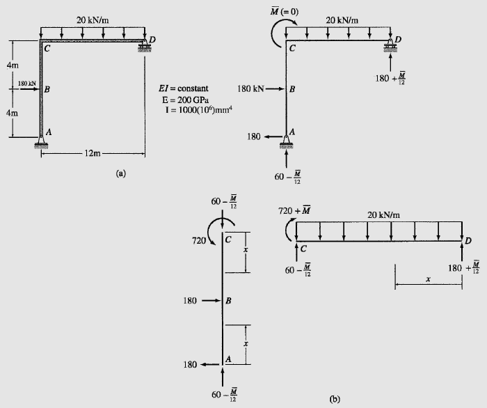
No external couple is acting at joint C, where the rotation is desired, so we apply a fictitious couple \overline{M} (= 0) at C, as shown in Fig. 7.23(b). The x coordinates used for determining the bending moment equations for the three segments of the frame are also shown in Fig. 7.23(b), and the equations for M in terms of \overline{M} and ∂M/∂\overline{M} obtained for the three segments are tabulated in Table 7.12. The rotation of joint C of the frame can now be determined by setting \overline{M} = 0 in the equations for M and ∂M/∂\overline{M} and by applying the expression of Castigliano’s second theorem as given by Eq. (7.65):
θ = ∑∫(\frac{∂M}{∂\overline{M}}) \frac{M}{EI}dx (7.65)
θ_C = ∑∫(\frac{∂M}{∂\overline{M}}) \frac{M}{EI}dx= \int_{0}^{12}{(\frac{x}{12})(180x – 20 \frac{x^2}{2}) dx}
= \frac{4320 kN-m^2}{EI} = \frac{4320}{200(10^6)1000(10^{-6})} = 0.0216 rad
θ_C = 0.0216 rad ![]()
| TABLE 7.12 | ||||
| Segment | x Coordinate | M (kN-m) | \frac{∂M}{∂\overline{M}} (\frac{kN-m}{kN-m}) | |
| Origin | Limits (m) | |||
| AB | A | 0-4 | 180x | 0 |
| CB | C | 0-4 | 720 | 0 |
| DC | D | 0-12 | (180 + \frac{\overline{M}}{12})x – 20\frac{x^2}{2} | \frac{x}{12} |