Question 15.4: Determining the Gasket Stiffness and Joint Constant Problem ...
Determining the Gasket Stiffness and Joint Constant
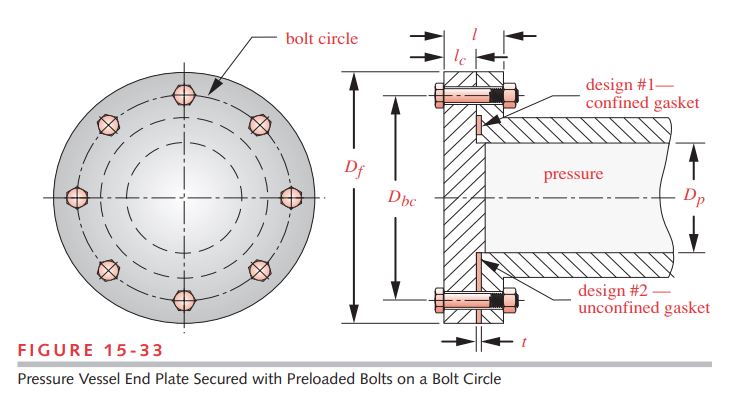
Problem A pressure chamber is sealed by a gasketed cap fastened with eight preloaded bolts. Find the gasket stiffness and joint constants for two designs of the assembly as shown in Figure 15-33, one with a confined gasket and one with an unconfined gasket. Also determine the loads felt by bolts and material.
Given The cylinder diameter D_{p} = 4 in. Bolt circle diameter D_{bc} = 5.5 in. Outside flange diameter D_{f} = 7.25 in. The eight 3/8-16 UNC bolts are equispaced on the bolt circle. The flange on the steel chamber is 0.75 in thick. The aluminum cover thickness l_{c} = 1.125 in. The clamped length l of the joint is 1.875 in. The gasket thickness t = 0.125 in. The pressure in the cylinder is 1 500 psi.
Assumptions The gasket material is rubber.
Learn more on how we answer questions.
See Figure 15-33.
1 Figure 15-33 shows two alternate designs of gasket for the joint on the same view to save space. Whichever design is used, its gasket configuration will be present on both sides of the centerline. Don’t be confused by the depiction of different gaskets top and bottom; only one or the other will be used in the final assembly. We will deal first with the confined gasket configuration.
2 The force on each bolt can be found from the known pressure and cylinder dimensions, assuming that all bolts share the load equally. The total force on the end cap is
P_{\text {total }}=p A=p \frac{\pi D_p^2}{4}=1500 \frac{\pi(4)^2}{4}=18850 lb (a)
and the applied force P on each bolt is
P=\frac{P_{\text {total }}}{N_{\text {bolts }}}=\frac{18850}{8}=2356 lb (b)
3 First analyze the confined gasket case. A confined gasket allows the metal surfaces to contact just as if there were no gasket present. So the analysis of the material stiffness can ignore the confined gasket.
4 Determine the relevant ratios for this joint from equations 15-17. The joint aspect ratio is:
k_{b^{\prime}}=\left\lgroup 1+\frac{d}{l} \right\rgroup ^{-1} k_b \cong\left\lgroup 1+\frac{d}{l} \right\rgroup ^{-1} \frac{A_t A_b}{A_b l_t+A_t l_s} E_b (15.17)
j=\frac{d}{l}=\frac{0.375}{1.875}=0.200 (c)
5 There are two plate to bolt moduli of interest here since we have different materials in the joint. We will call them r_{H} for the high modulus material (the steel cylinder flange) and r_{L} for the low modulus aluminum cover plate.
\begin{array}{l} r_H=\frac{E_{\text {material }}}{E_{\text {bolt }}}=\frac{30 E 6}{30 E 6}=1.0 \\ r_L=\frac{E_{\text {material }}}{E_{\text {bolt }}}=\frac{10.4 E 6}{30 E 6}=0.347 \end{array} (d)
6 The plate thickness ratio relates the thicknesses of the low and high modulus materials in the joint.
t=\frac{T_L}{T_L+T_H}=\frac{1.125}{1.125+0.750}=0.600 (e)
7 Calculate the Cr terms C_{H} and C_{L} for r_{H} and r_{L}, respectively, using equation 15.19 and the coefficients p_i from Table 15-8. For j = 0.20, they are: p_{0} = 0.6118, p_{1} = –1.1715, p_{2} = 1.0875, and p_{3} = –0.3806.
C_r=p_3 r^3+p_2 r^2+p_1 r+p_0 (15.19)
\begin{aligned} C_L &=C_r=p_3 r_L^3+p_2 r_L^2+p_1 r_L+p_0 \\ &=-0.381(0.347)^3+1.088(0.347)^2-1.172(0.347)+0.612=0.321 \end{aligned} (f)
Note that r_{H} = 1 so C_{H} is:
\begin{aligned} C_H &=C_r=p_3 r_H{ }^3+p_2 r_H{ }^2+p_1 r_H+p_0 \\ &=-0.381+1.088-1.172+0.612=0.147 \end{aligned} (g)
8 Because j > 0.1 in this example, we need to use equation 15.20b to calculate C_{t}. The coefficients q_{i} are taken from Table 15-9 and for j = 0.20, they are: q_{0} = 0.101, q_{1} = 8.547, q_{2} = –24.166, and q_{3} = 15.497.
\begin{array}{l} C_t=q_3 t^3+q_2 t^2+q_1 t+q_0 \\ C_t=15.497(0.60)^3-24.166(0.60)^2+8.547(0.60)+0.101=-0.124 \end{array} (h)
9 Calculate the amplitude of the correction factor to the linearized estimate using equation 15.21.
a=e^{0.0598(\ln j)^3+0.1385(\ln j)^2-0.4350(\ln j)-2.3516}=0.214 (i)
10 The joint stiffness factor for the confined-gasket design is calculated with equation 15.22.
\begin{aligned} C &=C_H+\left(t+a C_t\right)\left(C_L-C_H\right) \\ &=0.321+[0.60+0.214(-0.124)](0.321-0.147)=0.247 \end{aligned} (j)
11 The portions of the applied load P felt by the bolt and the material can now be found from equations 15.13.
\Delta \delta=\frac{P_b}{k_b}=\frac{P_m}{k_m} (15.13a)
P_b=\frac{k_b}{k_m} P_m (15.13b)
P_b=\frac{k_b}{k_m+k_b} P \\ P_b=C P \quad \text { where } \quad C=\frac{k_b}{k_m+k_b} (15.13c)
P_m=\frac{k_m}{k_b+k_m} P=(1-C) P (15.13d)
\begin{array}{l} P_b=C P=0.247(2356) \cong 581.1 lb \\ P_m=(1-C) P=(1-0.247)(2356) \cong 1775.1 lb \end{array} (k)
12 We can estimate the bolt stiffness k_{b^{\prime}} from equation 15.17 using its shank area = 0.110 in² and tensile stress area = 0.077 in² (Table 15-1), then estimate the material stiffness k_{m_1} for the confined gasket case by using equation 15.13c, given k_{b^{\prime}} and C.
k_{b^{\prime}}=\left\lgroup 1+\frac{d}{l} \right\rgroup ^{-1} k_b \cong\left\lgroup 1+\frac{d}{l} \right\rgroup ^{-1} \frac{A_t A_b}{A_b l_t+A_t l_s} E_b (15.17)
P_b=\frac{k_b}{k_m+k_b} P \\ P_b=C P \quad \text { where } \quad C=\frac{k_b}{k_m+k_b} (15.13c)
\begin{aligned} \text {length of thread :} \quad l_{\text {thd }} &=2 d+0.25=2(0.375)+0.25=1.0 \text { in } \\ \text {length of shank :} \quad l_s &=l_{\text {bolt }}-l_{\text {thd }}=2.25-1.0=1.25 \text { in } \\ \text {length of clamped thread :} \quad l_t &=l-l_s=1.875-1.25=0.625 \text { in } \end{aligned}
\begin{aligned} k_{b^{\prime}} & \cong\left\lgroup 1+\frac{d}{l} \right\rgroup^{-1} \frac{A_t A_b}{A_b l_t+A_t l_s} E_b \\ k_{b^{\prime}} & \cong\left\lgroup 1+\frac{0.375}{1.875} \right\rgroup^{-1} \frac{0.077(0.110)}{0.110(0.625)+0.077(1.25)} 30 E 6=1.290 E 6 lb / \text { in } \\ C &=\frac{k_{b^{\prime}}}{k_{m_1}+k_{b^{\prime}}} \Rightarrow k_{m_1}=k_{b^{\prime}} \frac{1-C}{C}=1.29 E 6\left\lgroup \frac{1-0.247}{0.247} \right\rgroup=3.940 E 6 lb / in \end{aligned} (l)
13 Now we will address the unconfined-gasket case. The bolt stiffness is not affected by the gasket but the material stiffness is. We now have two springs in series, the metal whose stiffness k_{m} is defined in equation (l) and the gasket which is calculated in equation (n) below. These combine according to equation 14.2b (p. 787). The portion of the unconfined gasket subjected to the clamp force can be assumed to be from the outside diameter of the flange shown in Figure 15-33 to the inside diameter of the vessel. The bolt hole should be subtracted from the gasket area. The area of the clamped gasket around one bolt is:
\frac{1}{k_{\text {total }}}=\frac{1}{k_1}+\frac{1}{k_2}+\frac{1}{k_3}+\ldots+\frac{1}{k_n} (14.2b)
A_g=\frac{\pi}{4}\left[\frac{\left(D_f^2-D_p^2\right)}{N_{b o l t s}}-d^2\right]=\frac{\pi}{4}\left[\frac{\left(7.25^2-4^2\right)}{8}-0.375^2\right]=3.479 in ^2 (m)
14 The stiffness of this piece of gasket is found from equation 15.11c (p. 885).
k_m=\frac{A_m E_m}{l} (15.11c)
k_{m_2}=k_g=\frac{A_g E_g}{t}=\frac{3.479(10 E 3)}{0.125} \cong 2.783 E 5 lb / in (n)
The modulus of elasticity E_{g} of the gasket material is found in Table 15-10 (p. 900).
15 The combined stiffness of the gasketed joint (from equation 14.2b, p. 787) is
\frac{1}{k_{\text {total }}}=\frac{1}{k_1}+\frac{1}{k_2}+\frac{1}{k_3}+\ldots+\frac{1}{k_n} (14.2b)
k_m=\frac{1}{\frac{1}{k_{m_1}}+\frac{1}{k_{m_2}}}=\frac{1}{\frac{1}{3.94 E 6}+\frac{1}{2.783 E 5}} \cong 2.600 E 5 lb / in (o)
Note that the combined stiffness is essentially the same as that of the soft gasket alone, since it dominates the equation. We could have used the gasket stiffness k_{g} to represent the joint stiffness k_{m} with little error.
16 The joint constant with the unconfined gasket is now
\begin{array}{c} C=\frac{k_{b^{\prime}}}{k_m+k_{b^{\prime}}}=\frac{1.290 E 6}{2.600 E 5+1.290 E 6}=0.832 \\ \text {and} \quad (1-C)=0.168 \end{array} (p)
17 The portions of the applied load P felt by the bolt and the material with a soft, unconfined gasket in the joint can now be found from equations 15.13 (p. 886).
\Delta \delta=\frac{P_b}{k_b}=\frac{P_m}{k_m} (15.13a)
P_b=\frac{k_b}{k_m} P_m (15.13b)
P_b=\frac{k_b}{k_m+k_b} P \\ P_b=C P \quad \text { where } \quad C=\frac{k_b}{k_m+k_b} (15.13c)
P_m=\frac{k_m}{k_b+k_m} P=(1-C) P (15.13d)
\begin{array}{l} P_b=C P=0.832(2356) \cong 1961 lb \\ P_m=(1-C) P=(1-0.832)(2356) \cong 395 lb \end{array} (q)
18 See what has happened as a result of introducing an unconfined soft gasket. Compare the value of C in equation (j) to C in equation (p). The bolt has gone from feeling only 25% of the applied load with no gasket (or a confined gasket) to feeling 83% of the applied load with a soft, unconfined gasket. In effect, the roles of the bolt and the material have been reversed by the introduction of the soft gasket. An unconfined, soft gasket severely limits the ability of the bolt to accommodate fatigue loads, as was accomplished in the previous example. The files EX15-04 can be found on the CD-ROM.
| Table 15-8 Parameters for Equation 15.19 | ||||
| j | p_{0} | p_{1} | p_{2} | p_{3} |
| 0.10 | 0.4389 | –0.9197 | 0.8901 | –0.3187 |
| 0.20 | 0.6118 | –1.1715 | 1.0875 | –0.3806 |
| 0.30 | 0.6932 | –1.2426 | 1.1177 | –0.3845 |
| 0.40 | 0.7351 | –1.2612 | 1.1111 | –0.3779 |
| 0.50 | 0.7580 | –1.2632 | 1.0979 | –0.3708 |
| 0.60 | 0.7709 | –1.2600 | 1.0851 | –0.3647 |
| 0.70 | 0.7773 | –1.2543 | 1.0735 | –0.3595 |
| 0.80 | 0.7800 | –1.2503 | 1.0672 | –0.3571 |
| 0.90 | 0.7797 | –1.2458 | 1.0620 | –0.3552 |
| 1.00 | 0.7774 | –1.2413 | 1.0577 | –0.3537 |
| 1.25 | 0.7667 | –1.2333 | 1.0548 | –0.3535 |
| 1.50 | 0.7518 | –1.2264 | 1.0554 | –0.3550 |
| 1.75 | 0.7350 | –1.2202 | 1.0581 | –0.3574 |
| 2.00 | 0.7175 | –1.2133 | 1.0604 | –0.3596 |
| Table 15-9 Parameters for Equation 15.20 | ||||||
| j | q_{0} | q_{1} | q_{2} | q_{3} | q_{4} | q_{5} |
| 0.10 | 0.0079 | 17.0400 | –92.832 | 202.44 | –209.38 | 82.726 |
| 0.20 | 0.1010 | 8.5465 | –24.166 | 15.497 | ||
| 0.30 | 0.0861 | 8.2344 | –22.274 | 13.963 | ||
| 0.40 | 0.0695 | 8.0297 | –20.727 | 12.646 | ||
| 0.50 | 0.0533 | 7.8676 | –19.357 | 11.457 | ||
| 0.60 | 0.0372 | 7.6705 | –17.951 | 10.262 | ||
| 0.70 | 0.0197 | 7.3030 | –16.235 | 8.9273 | ||
| 0.80 | 0.0029 | 6.9893 | –14.737 | 7.7545 | ||
| 0.90 | –0.0123 | 6.7006 | –13.363 | 6.6784 | ||
| 1.00 | –0.0265 | 6.4643 | –12.188 | 5.7481 | ||
| 1.25 | –0.0524 | 5.7363 | –9.3326 | 3.6348 | ||
| 1.50 | –0.0678 | 5.0674 | –7.0322 | 2.0107 | ||
| 1.75 | –0.0763 | 4.5187 | –5.1590 | 0.6861 | ||
| 2.00 | –0.0784 | 3.9617 | –3.5248 | –0.3956 | ||
| Table 15-1 Principal Dimensions of Unified National Standard Screw Threads Data Calculated from Equations 15.1—See Reference 3 for More Information |
|||||||
| Coarse Threads—UNC | Fine Threads—UNF | ||||||
| Size | Major Diameter d (in) | Threads per inch | Minor Diameter d_{r} (in) | Tensile Stress Area A_{t} (in^2) | Threads per inch | Minor Diameter d_{r} (in) | Tensile Stress Area A_{t} (in^2) |
| 0 | 0.0600 | – | – | – | 80 | 0.0438 | 0.0018 |
| 1 | 0.0730 | 64 | 0.0527 | 0.0026 | 72 | 0.0550 | 0.0028 |
| 2 | 0.0860 | 56 | 0.0628 | 0.0037 | 64 | 0.0657 | 0.0039 |
| 3 | 0.0990 | 48 | 0.0719 | 0.0049 | 56 | 0.0758 | 0.0052 |
| 4 | 0.1120 | 40 | 0.0795 | 0.0060 | 48 | 0.0849 | 0.0066 |
| 5 | 0.1250 | 40 | 0.0925 | 0.0080 | 44 | 0.0955 | 0.0083 |
| 6 | 0.1380 | 32 | 0.0974 | 0.0091 | 40 | 0.1055 | 0.0101 |
| 8 | 0.1640 | 32 | 0.1234 | 0.0140 | 36 | 0.1279 | 0.0147 |
| 10 | 0.1900 | 24 | 0.1359 | 0.0175 | 32 | 0.1494 | 0.0200 |
| 12 | 0.2160 | 24 | 0.1619 | 0.0242 | 28 | 0.1696 | 0.0258 |
| 1/4 | 0.2500 | 20 | 0.1850 | 0.0318 | 28 | 0.2036 | 0.0364 |
| 5/16 | 0.3125 | 18 | 0.2403 | 0.0524 | 24 | 0.2584 | 0.0581 |
| 3/8 | 0.3750 | 16 | 0.2938 | 0.0775 | 24 | 0.3209 | 0.0878 |
| 7/16 | 0.4375 | 14 | 0.3447 | 0.1063 | 20 | 0.3725 | 0.1187 |
| 1/2 | 0.5000 | 13 | 0.4001 | 0.1419 | 20 | 0.4350 | 0.1600 |
| 9/16 | 0.5625 | 12 | 0.4542 | 0.1819 | 18 | 0.4903 | 0.2030 |
| 5/8 | 0.6250 | 11 | 0.5069 | 0.2260 | 18 | 0.5528 | 0.2560 |
| 3/4 | 0.7500 | 10 | 0.6201 | 0.3345 | 16 | 0.6688 | 0.3730 |
| 7/8 | 0.8750 | 9 | 0.7307 | 0.4617 | 14 | 0.7822 | 0.5095 |
| 1 | 1.0000 | 8 | 0.8376 | 0.6057 | 12 | 0.8917 | 0.6630 |
| 1 1/8 | 1.1250 | 7 | 0.9394 | 0.7633 | 12 | 1.0167 | 0.8557 |
| 1 1/4 | 1.2500 | 7 | 1.0644 | 0.9691 | 12 | 1.1417 | 1.0729 |
| 1 3/8 | 1.3750 | 6 | 1.1585 | 1.1549 | 12 | 1.2667 | 1.3147 |
| 1 1/2 | 1.5000 | 6 | 1.2835 | 1.4053 | 12 | 1.3917 | 1.5810 |
| 1 3/4 | 1.7500 | 5 | 1.4902 | 1.8995 | |||
| 2 | 2.0000 | 4.5 | 1.7113 | 2.4982 | |||
| 2 1/4 | 2.2500 | 4.5 | 1.9613 | 3.2477 | |||
| 2 1/2 | 2.5000 | 4 | 2.1752 | 3.9988 | |||
| 2 3/4 | 2.7500 | 4 | 2.4252 | 4.9340 | |||
| 3 | 3.0000 | 4 | 2.6752 | 5.9674 | |||
| 3 1/4 | 3.2500 | 4 | 2.9252 | 7.0989 | |||
| 3 1/2 | 3.5000 | 4 | 3.1752 | 8.3286 | |||
| 3 3/4 | 3.7500 | 4 | 3.4252 | 9.6565 | |||
| 4 | 4.0000 | 4 | 3.6752 | 11.0826 | |||
| Table 15-10 Young’s Modulus for Some Gasket Materials Source: Reference 12 with permission of McGraw-Hill, Inc., New York |
||
| Material | Modulus of Elasticity | |
| psi | MPa | |
| Cork | 12.5E3 | 86 |
| Compressed asbestos | 70E3 | 480 |
| Copper-asbestos | 13.5E6 | 93E3 |
| Copper (pure) | 17.5E6 | 121E3 |
| Plain rubber | 10E3 | 69 |
| Spiral wound | 41E3 | 280 |
| Teflon | 35E3 | 240 |
| Vegetable fiber | 17E3 | 120 |