Question 17.SP.6: Each of the two slender rods shown is 0.75 m long and has a ...
Each of the two slender rods shown is 0.75 m long and has a mass of 6 kg. If the system is released from rest with β = 60°, determine (a) the angular velocity of rod AB when β = 20°, (b) the velocity of point D at the same instant.
STRATEGY: You have two positions and are interested in velocities, so use the conservation of energy. You will also need to use kinematics to relate the velocity terms in the kinetic energy expression.
MODELING: Choose the system to be both bars and model them as rigid bodies.
Learn more on how we answer questions.
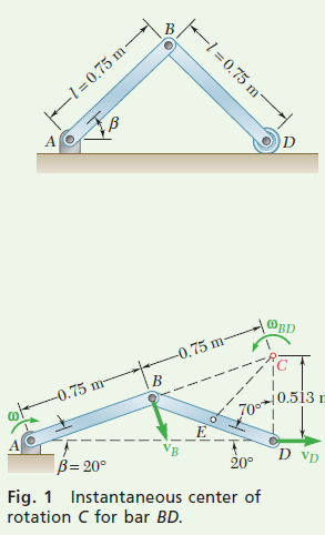
ANALYSIS: To illustrate that the order in which you solve a problem doesn’t matter, let’s start with kinematics.Kinematics of Motion When β = 20°. Since \nu_B is perpendicular to the rod A_B and \nu_D is horizontal, the instantaneous center of rotation of rod BD is located at C (Fig. 1). From the geometry of the figure, you obtain
B C=0.75 \mathrm{~m} \quad C D=2(0.75 \mathrm{~m}) \sin 20^{\circ}=0.513 \mathrm{~m}
Apply the law of cosines to triangle CDE, where E is located at the mass center of rod BD. You find EC = 0.522 m. Denoting the angular velocity of rod AB by ω, you have (Fig. 2)
\begin{aligned}\bar{\nu}_{A B} &=(0.375 \mathrm{~m}) \omega & \overline{\mathbf{v}}_{A B} &=0.375 \omega \searrow \\\nu_B &=(0.75 \mathrm{~m}) \omega & \mathrm{v}_B &=0.75 \omega \searrow\end{aligned}
Since rod BD seems to rotate about point C, you have
\begin{aligned}\nu_B=&(B C) \omega_{B D} \quad(0.75 \mathrm{~m}) \omega=(0.75 \mathrm{~m}) \omega_{B D} \quad \omega_{B D}=\omega \circlearrowleft \\& \bar{\nu}_{B D}=(E C) \omega_{B D}=(0.522 \mathrm{~m}) \omega \quad \overline{\mathbf{v}}_{B D}=0.522 \omega \searrow\end{aligned}
Conservation of Energy. Since there are no springs in the system
T_1 + V_{\mathrm{g}_1}=T_2 + V_{\mathrm{g}_2}
You first need to determine the energy at the two positions.
Position 1.
Potential Energy. Choose the datum as shown in Fig. 3, and observe that W=(6 \mathrm{~kg})\left(9.81 \mathrm{~m} / \mathrm{s}^2\right)=58.86 \mathrm{~N}. Then you have
V_{\mathrm{g}_1}=2 W \bar{y}_1=2(58.86 \mathrm{~N})(0.325 \mathrm{~m})=38.26 \mathrm{~J}
Kinetic Energy. Initially, the system is at rest, so T_1 = 0.
Position 2.
Potential Energy. Compute the new height of the mass centers of the rods to be \bar{y}_2=0.75 \sin (20)=0.1283 \mathrm{~m} (Fig. 4).
V_{\mathrm{s}_2}=2 W \bar{y}_2=2(58.86 \mathrm{~N})(0.1283 \mathrm{~m})=15.10 \mathrm{~J}
Kinetic Energy.
\begin{aligned}I_{A B} &=\bar{I}_{B D}=\frac{1}{12} m l^2=\frac{1}{12}(6 \mathrm{~kg})(0.75 \mathrm{~m})^2=0.281 \mathrm{~kg} \cdot \mathrm{m}^2 \\T_2 &=\frac{1}{2} m \bar{\nu}_{A B}^2 + \frac{1}{2} \bar{I}_{A B} \omega_{A B}^2 + \frac{1}{2} m \bar{\nu}_{B D}^2 + \frac{1}{2} \bar{I}_{B D} \omega_{B D}^2 \\&=\frac{1}{2}(6)(0.375 \omega)^2 + \frac{1}{2}(0.281) \omega^2 + \frac{1}{2}(6)(0.522 \omega)^2 + \frac{1}{2}(0.281) \omega^2 \\&=1.520 \omega^2 \end{aligned}
Conservation of Energy. Now you can write
\begin{aligned}T_1 + V_{\mathrm{g}_1} &=T_2 + V_{\mathrm{g}_2} \\0 + 38.26 \mathrm{~J} &=1.520 \omega^2 + 15.10 \mathrm{~J} \\\omega &=3.90 \mathrm{rad} / \mathrm{s} \quad \omega_{A B}=3.90 \mathrm{rad} / \mathrm{s} \circlearrowright \end{aligned}
Velocity of Point D.
\begin{aligned}\nu_D=(C D) \omega=(0.513 \mathrm{~m})(3.90 \mathrm{rad} / \mathrm{s})=& 2.00 \mathrm{~m} / \mathrm{s} \\& \mathbf{v}_D=2.00 \mathrm{~m} / \mathrm{s} \rightarrow\end{aligned}
REFLECT and THINK: The only step in which you need to use forces is when calculating the gravitational potential energy in each position. However, it is good engineering practice to show the complete free-body diagram in each case to identify which, if any, forces do work. Rather than use the instantaneous center of rotation, you could have also used vector algebra to relate the velocities of the various objects.


