Question 8.CS.1D: FEA Analysis of a Bicycle Brake Lever Problem A bicycle brak...
FEA Analysis of a Bicycle Brake Lever
Problem A bicycle brake lever was analyzed for stress and deflection with classical methods and simplified geometry in Case Study 1B (p. 206). Analyze this assembly with FEA and compare the results to the earlier study.
Given The geometry and loading are known from Case Study 1A (p. 79) and a classical stress analysis was done in Case Study 1B (p .206). The average human’s hand can develop a grip force of about 267 N (60 lb) in the lever position shown.
Assumptions A static analysis is acceptable due to a small number of load cycles.
Learn more on how we answer questions.
See Figures 8-32 to 8-33.
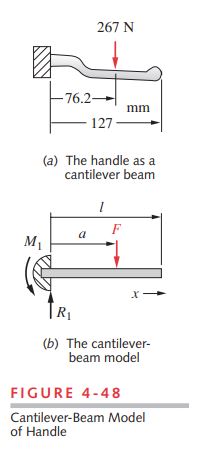
1 Figure 3-1 shows the brake lever assembly and Figure 4-48 shows the simplified model of the lever geometry, loads, and constraints that were used for the classical solution of Case Study 1B. The complex geometry of the handle had to be ignored and it was modeled as a straight cantilever beam cut or truncated where the handle joins the pivot block. A solid model of the arm that accurately captures the geometry is easily created in CAD. Finite element analysis can then be applied.
2 As a first step, a model of the truncated beam of Figure 4-48a that was analyzed in the previous study was created but with its real geometry. Figure 8-32a shows the solid model with load and boundary conditions applied as a cantilever beam. Figure 8-32b shows the mesh, and Figure 8-32c shows the stress contour plot. The mesh uses 16thorder tetrahedral elements with 16 nodes per side. The highest stress is at the point labeled P in the figure and is 69.63 MPa. This compares to a value of 70.9 MPa from the classical analysis that assumed a round cross section for the handle at that point. The FEA model has an oval cross section. These numbers agree within 2%, which points out the value of a simple model such as was used in the classical solution. The FEA solution involved more work in this case than the classical solution. That will not always be the case as parts of very complex geometry are difficult to model by classical methods. The classical method gives a deflection of 0.54 mm and this FEA model gives 0.69 mm due to the real arm geometry being less stiff than in Figure 4-48b.
3 With the ability to model complex geometry, we can create a model in FEA that includes the parts of the assembly that were ignored in the truncated model of Figure 4-48, namely the pivot block end of the handle, pivot pin, and cable. Figure 8-33 shows a model that includes these details.
4 Figure 8-33a shows the complete handle attached to a base of arbitrary shape by kinematic constraints around the pin on the base that fits the hole in the handle. The cable end has a cylindrical lug that fits in the open hole of the handle and its interaction with the handle is also defined by kinematic constraints on the half of the hole surface that bears the cable-lug load. The hand load is applied to the handle and is balanced by the cable load along with reaction forces at the fixed boundary conditions at the bottom of the base. This arrangement closely mimics the actual loading on the handle.
5 Figure 8-33b shows the meshed model of the handle alone. Base and cable end were also meshed and the system solved as an assembly in FEA. The finest mesh available was used and the elements are all 16th order tetrahedra. Figure 8-33c shows stress distributions in the pivot block and handle where they are greatest. The highest tensile stress is at the juncture of the handle and pivot block (labeled P) where the stress concentration of that corner raises the stress to 98.12 MPa. This is 1.4 times the 69.63 MPa calculated with the simpler truncated model, meaning that this corner has a stress concentration factor K_{c} = 1.4. The truncated model cannot give information on the stress concentration because the sharp corner does not exist in that model. In that sense this more complicated model is superior, but it took a lot more time and effort to do. As an alternative, the classical solution could estimate a stress concentration factor for the corner and obtain a better estimate of stress with less time and effort than needed for this FEA solution. Point Q also has elevated stress in the sharp corner. This could be improved by redesigning it to have a full radius at the end of that slot. The stress at R was estimated as 91.9 MPa in the classical model and is 100.6 MPa in this more accurate FEA model. Deflection at the end of the handle in the complete model is 0.98 mm. A Solidworks model of this study is in the folder Case 1-D on the CD-ROM.