Question 14.1: FINDING THE PERFORMANCE OF A SEPARATELY EXCITED MOTOR CONTRO...
FINDING THE PERFORMANCE OF A SEPARATELY EXCITED MOTOR CONTROLLED BY A DC–DC CONVERTER
The armature of a separately excited DC motor is controlled by a DC–DC converter operating at a frequency of f_{c} = 1 kHz and a duty cycle of k = 0.8. The DC–DC supply voltage to the armature is V_{s} = 220 V. The field current is also controlled by a DC–DC converter operating at a frequency of f_{s} = 1 kHz and a duty cycle of δ = 0.5. The DC supply voltage to the field is V_{f} = 280 V. The motor parameters are:
Armature resistance, R_{m} = 0.1 Ω
Armature inductance, L_{m} = 10 mH
Field resistance, R_{f} = 10 Ω
Field inductance, L_{f}= 20 mH
Back-emf constant, K = 0.91
Viscous torque constant, B = 0.3
Motor inertia, J = 1
Load torque, T_{L} = 50, 100, and 150 N⋅m
Use PSpice to plot the transient response of the armature and field current, the
torque developed, and the motor speed for a duration of 0 to 30 msec in steps of
10 μsec.
Learn more on how we answer questions.
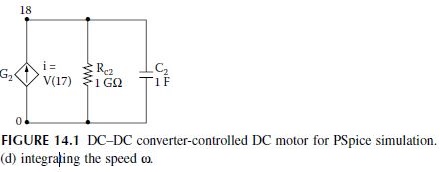
The armature and field circuits for PSPice simulation are shown in Figure 14.1(a) and Figure 14.1(b), respectively. The net torque, which is obtained by subtracting the viscous (T_{B}) and load torque (T_{L}) from the torque developed (T_{d}), is integrated to obtain the motor speed as shown in Figure 14.1(c). The motor speed is integrated to obtain the shaft position as shown in Figure 14.1(d).
The PSpice schematic is shown in Figure 14.2, which comprises three separate blocks: the motor field, motor armature, and motor load consisting of inertia J and viscous torque constant B. It has one pulse-width modulated (PWM) generator for the armature control and one PWM generator for the motor field control. The listing of the circuit file is as follows:
| SOURCE VS 1 0 DC 220V ; Armature supply
PARAM Duty_a=0.5 ; duty cycle of the armature circuit CIRCUIT .PARAM VISCOUS = 0.3 ; Viscous constant .PARAM J = 1 ; Motor inertia ANALYSIS . TRAN 10US 30MS UIC ; Transient analysis with initial condition . END |
The plots of the transient response for the armature I(VX) and field currents I(VY) are shown in Figure 14.3. The plots for the torque developed V(12,13) and the motor speed V(17) are shown in Figure 14.4. The field current shown has not reached steady-state conditions. The armature current reaches a peak before settling down. The torque is pulsating because of pulsating armature and field currents.