Question 8.1: Finite Element Analysis of a Notched Cantilever Beam Problem...
Finite Element Analysis of a Notched Cantilever Beam
Problem: A notched, rectangular cross-section cantilever beam is loaded in bending by a fully-reversed transverse force. Determine a reasonable finite element mesh and compare its prediction of maximum stress and deflection with a closed form solution for points at the beam end l, distance b, and the notch at a.
Given: The beam dimensions in Figure 8-7a are: a = 4, d = 7.5, l = 10, b = 0.1, h = 1, and r = 0.167 in. The load F = 25 lb. The material is steel.
Assumptions: The supporting wall is considered to be much stiffer than the beam. Beam weight is negligible compared to the applied load. The reduction in beam cross section due to the notch has a minimal effect on the total beam deflection, but a significant effect on the local stress. A 2-D FEA model is sufficient as plane stress may be assumed.

Learn more on how we answer questions.
1 First do a closed-form solution to determine the theoretical values of stress and deflection. Figure 8-7b shows an FBD and the shear and moment diagrams for this beam. Three locations are of interest, the beam outer fibers at the wall, also at D, and in the root of the notch at A where there is stress concentration. At the wall the moment magnitude is Fl = 250 in-lb and the bending stress in the outer fiber is:
\sigma=\frac{M c}{I}=\frac{250(0.5)}{\frac{0.1(1)^3}{12}}=\frac{125}{0.0083}=15000 psi (a)
Point D provides a check on a stress away from any concentrations.* At distance d from the wall the moment is F(l – d) = 25(10 – 7.5) = 62.5 in-lb and the bending stress in the outer fiber at point D is:
\sigma=\frac{M c}{I}=\frac{62.5(0.5)}{0.1(1)^3 / 12}=3750 psi (b)
At the notch the stress concentration factor from Figure E-12 is:
K_t=A\left\lgroup\frac{r}{d}\right\rgroup^b=0.98315\left\lgroup\frac{0.167}{1-2(0.167)}\right\rgroup^{-0.33395}=1.56 (c)
The moment magnitude is F(l – a) = 25(10 – 4) = 150 in lb and the local bending stress at the notch is:
\sigma=K_t \frac{M c}{I}=1.56 \frac{150(0.5-0.167)}{\frac{0.1\left[1-2(0.167)^3\right]}{12}}=1.56 \frac{49.950}{0.00246}=31676 psi (d)
2 The equation for maximum deflection due to bending is found in Figure D-1:
y_{\max }=-\frac{F l^3}{3 E I}=\frac{25(10)^3}{3(30 E 6)(0.0083)}=-0.0335 \text { in } (e)
3 Quad elements are preferred to triangular, so they will be used. Figure 8-8 shows four mesh conditions used. Table 8-1 shows the stresses calculated at point D and at the notch for each of these mesh conditions. Figure 8-9 plots the stresses at the notch against mesh size. Convergence to the analytically calculated value at point D is more rapid than at the notch because of the absence of stress concentration there.†
But the “very fine” mesh of Figure 8-8d is needed to get good convergence at the notch. The differences between the FEA stresses calculated at point D at various mesh sizes and the analytical value is due in part to the fact that the analytical stress is calculated at the outer fiber, but the FEA stresses shown are an average of stresses calculated at the 4 integration points for each element, and so differ depending on element size. Other options are to report the FEA stresses at the element nodes or at the integration points, giving 4 values per quad element.
4 Table 8-2 shows the FEA estimates of deflection on the neutral axis at the beam tip for each mesh size compared to the analytical deflection solution. Note that there is little difference between the results with these very different mesh sizes which points out that a fine mesh is not as necessary for accurate deflections as for local stresses. Also note that the FEA deflections are all larger than the analytical. This is because the FEA solution includes the effects of deflection due to transverse shear, which is not accounted for in the bending deflection equation (e) but can be significant if the beam is short. Here it adds 10% to the bending deflection.
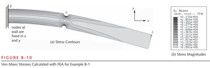
5 Figure 8-10 shows the distribution of von Mises stresses in the beam as calculated by FEA. These include the transverse shear stress. Note the stress concentrations at the notches (point A) and at the tip of the beam where the load was applied (L). The analytical solution did not automatically calculate these stress concentrations. We had to recognize the need to apply a stress concentration factor to the stress calculation at the notch. Unless we also did so at the point of load application, we would not see the increased stress there. It is not as easy to see in this figure but there is also some stress concentration at the beam root (R) where the boundary condition at the wall causes a local stress increase. FEA (using 2-D or higher elements) has the advantage of automatically revealing stress concentrations, whether due to local geometry, or locally applied forces and boundary conditions. But, you need to make sure that you have a properly converged mesh especially around areas of potential stress concentration or your results may have large errors as can be seen in Table 8-1 and Figure 8-9.
| Table 8-1 FEA Stresses Versus Mesh Size in Example 8-1 |
||
| Elements | Stress (psi) | |
| @Pt. D | @ Notch | |
| 535 | 3158 | 17128 |
| 1146 | 3167 | 21710 |
| 15688 | 3653 | 27801 |
| 97797 | 3713 | 30363 |
| analytical | 3750 | 31676 |
| Table 8-2 Deflection Versus Mesh Size in Example 8-1 |
|
| Elements | Deflection (in) |
| 535 | 0.0359 |
| 1146 | 0.0364 |
| 15688 | 0.0368 |
| 97797 | 0.0369 |
| analytical | 0.0335 |
* By St. Venant’s principle, stresses at locations away from the point of application of forces or reactions will be unaffected by the area of contact of the force.
† Note that it is not necessary to refine the mesh over the entire part as was done here. It would have been sufficient to refine it locally around the notch where stress concentration is present. For this example, the entire mesh was refined in order to show the effects at point D far from the notch, as well as at the notch.