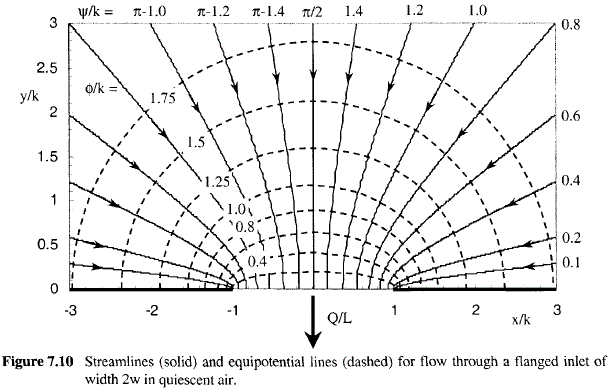
Question 7.3: Flanged Slot of Finite Width in Quiescent Air Consider a slo...
Flanged Slot of Finite Width in Quiescent Air
Consider a slot in an infinite plane as shown in Figure 7.10. The width of the slot is 2w (w = 0.020 m) and the aspect ratio of the slot is very large, L/w » 1. Air is withdrawn through the slot at a volumetric flow rate (Q/L) of 12.0 m²/min, which produces an average face velocity, U_{face} = 300. m/min. This corresponds favorably with typical slot velocities recommended by the ACGIH for different types of industrial ventilation hoods.
To do:
(a) Predict and plot several streamlines for this flow.
(b) Predict the normalized velocity components (U_\mathrm{x}/U_{face}and U_\mathrm{y}/U_{face}) and the normalized air speed,
\frac{U}{U_{face}} =\frac{\sqrt{U_\mathrm{x}^2+U_\mathrm{y}^2} }{U_{face}}
at points along the streamline ψ= Q/(2L). This is the streamline along the y-axis (x = 0), i.e. along the axis of the slot (axis of symmetry), normal to the slot face. Plot U/U_{face} as a function of the normalized radial distance to the center of the slot (r/w) along this streamline,
\frac{r}{\mathrm{w}} =\frac{\sqrt{x^2+y^2} }{\mathrm{w}}
Compare with the air speed that would exist if the slot were a line sink of strength Q/L.
(c) Predict the velocity components (U_x and U_y) at an arbitrary point (x,y). Find the velocity components at the particular point x = 0.63 m, y = 0.025 m.

Our explanations are based on the best information we have, but they may not always be right or fit every situation.
Learn more on how we answer questions.