Question 10.13: For the flat bar in Figure 10–42 welded along a seam at an a...
For the flat bar in Figure 10–42 welded along a seam at an angle of 20° CCW from the x-axis, the stress element aligned parallel with the x- and y-axes is subjected to these stresses:
\sigma_{x} = 400 MPa \sigma_{y} = -300 MPa \tau_{xy} = 200 MPa (CW)
Determine the stress condition on the element inclined at the 20° angle, aligned with the weld seam.

Learn more on how we answer questions.
Objective Draw the stress element aligned with the weld seam at 20° with the x-axis.
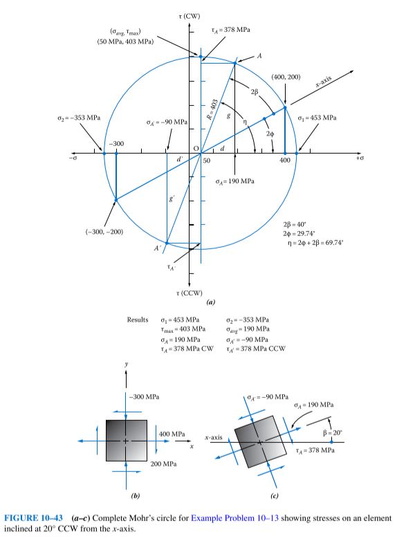
Given Note that the given stress element is the same as that used in Example Problem 10–5. The basic Mohr’s circle from that problem is shown in Figure 10–33, and it is reproduced in Figure 10–43 with additional construction described next.
Analysis Use the Procedure for Finding the Stress at a Specified Angle.
Results Steps 1 and 2 are shown on the original Mohr’s circle.
Step 3. The desired axis is one inclined at 20° CCW from the x-axis. Recalling that angles in Mohr’s circle are double the true angles, we can draw a line through the center of the circle at an angle of 2β = 40° CCW from the x-axis. The intersection of this line with the circle, labeled A in the figure, locates the point on the circle defining the stress condition of the desired element. The coordinates of this point (σ_{A} , τ_{A}) give the normal and shear stresses acting on one set of faces of the desired stress element.
Step 4. Simple trigonometry and the basic geometry of the circle can be used to determine σ_{A} and τ_{A} by projecting lines vertically and horizontally from point A to the σ- and τ-axes, respectively. The total angle from the σ-axis to the axis through point A, called η (eta) in the figure, is the sum of 2ϕ and 2β. In Example Problem 10–5. we found 2ϕ = 29.74°. Then,
η = 2ϕ + 2β = 29.74° + 40° = 69.74°
A triangle has been identified in Figure 10–43 with sides labeled d, g, and R. From this triangle, we can compute
d = R cos η = (403) cos 69.74° = 140
g = R sin η = (403) sin 69.74° = 378
These values enable the computation of
\sigma_{A} = O + d = 50 + 140 = 190 MPa
\tau_{A} = g = 378 MPa CW
where O indicates the value of the normal stress at the center of Mohr’s circle.
The stresses on the remaining set of faces of the desired stress element are the coordinates of the points A′ located 180° from A on the circle and, therefore, 90° from the faces on which (σ_{A} , τ_{A}) act. Projecting vertically and horizontally from A′ to the σ- and τ-axes locates σ_{A}and \tau_{A} . By similar triangles we can say that d′ = d and g′ = g. Then,
\sigma_{A'} = O – d’ = 50 – 140 = -90 MPa
\tau_{A'} = g’ = 378 MPa CCW
Comment Figure 10–43(c) shows the final element inclined at 20° from the x-axis. This is the stress condition experienced by the material along the weld line.