Question 4.9: For the given state of plane stress, construct Mohr’s circle...
For the given state of plane stress, construct Mohr’s circle, determine the principal stresses, and determine the maximum shearing stress and the corresponding normal stress (Figure 4.41).
Given: σx = 50 MPa, σy = –10 MPa, τxy = 40 MPa.
Find: Extreme stress states.
Assume: Plane stress: σz = τxz = τzy = 0.

Learn more on how we answer questions.
We outline the steps used to construct Mohr’s circle and make the necessary calculations. The steps are as follows:
Plot point X: ( \sigma _x, \tau_{xy}).
Plot point Y: ( \sigma _y, \tau_{xy}).
Draw line XY, which passes through the circle center: (σ_{ave}, 0).
Find radius R and draw in the circle.
1. Plot Point X: ( \sigma _x, \tau_{xy})
We note straight off that the shear stress given is “positive,” according to Figure 2.5, but we are not sure how to plot the point ( \sigma _x, \tau_{xy}) on Mohr’s circle. Finding \sigma _x on the σ axis is straightforward—the normal stress sign convention simply says that tensile stresses are positive and compressive are negative, but does \tau_{xy} lie above or below that axis? We know that for Mohr’s circle to work, we must have points X and Y on opposite sides of the σ axis so that their connecting line XY passes through the center of the circle. Our sign convention must ensure this. We therefore make use of a system based on the positive x (and y) faces of our unrotated element.
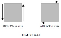
Looking at the positive x face of our initial element (right-hand face), we see that the component of shear stress on this face is tending to rotate the element counterclockwise. This tells us to plot point X below the σ axis. Our convention is that when this component tends to rotate clockwise, X is above the axis and when counterclockwise, it is below. (This somewhat awkward rule can be remembered by the equally strange mnemonic: “In the kitchen, the clock is above and the counter is below.”) We formalize this rule in Figure 4.42. Remember that we’ll apply this sign convention to points X and Y separately—for Mohr’s circle to work, we must have points X and Y on opposite sides of the σ axis.
2. Plot Point Y: ( \sigma _y, \tau_{xy}).
Following the same reasoning as for point X, we plot point Y to the left of the τ axis, as \sigma _y. is compressive, and above the σ axis, as the shear stress on the positive y (top) face of the element tends to rotate clockwise.
These two points may now be plotted on the στ axes (Figure 4.43).
3. Draw Line XY
This line (Figure 4.44) passes through the σ (horizontal) axis at the center of the circle:
(\sigma_{ave},0)=\left\lgroup\frac{\sigma _x+ \sigma _y}{2},0\right\rgroup = (20 MPa, 0)
4. Find the Radius R and Draw the Circle
We may use the geometry of the first three steps, or the formulas derived in the notes, to calculate the radius of the circle. Graphically, we see that R is the hypotenuse of a right triangle whose other legs have length 40 and 50 – 20 = 30. Thus, R = ((40)^2 + (30)^2)^{½} = 50 MPa. Alternatively,
R=\sqrt{\left\lgroup\frac{\sigma _x-\sigma _y}{2} \right\rgroup^2 +(\tau _{_{xy}})^2} = 50 MPa.
We can now sketch Mohr’s circle by hand, by using a compass, or by using a software package. The circle contains all the information we need about all possible axes and thus all possible stress states for the given element (Figure 4.45).
We can find, and label, the principal stresses:
\sigma _1=\sigma_{ave}+R =20 MPa + 50 MPa = 70 MPa.
\sigma _2=\sigma_{ave}-R =20 MPa – 50 MPa = -30 MPa.
This principal stress state (extreme normal stress, no shear stress) occurs when the axes are rotated by \textrm{θ} _N. (Or, when line XY is rotated around Mohr’s circle by 2\textrm{θ} _N.) We can find 2 \textrm{θ} _N using a protractor, or we can use our formulas: \textrm{θ} _N =½ \tan ^{-1}(2\textrm{τ} _{xy}/\sigma _x-\sigma _y). At this \textrm{θ} _N we can calculate that the value of σ_{x^\prime} (rather than σ_{y^\prime}) is 70 MPa, so we draw our properly oriented element that experiences this principal stress state (Figure 4.46).
Next, we calculate the maximum shear stress and the corresponding normal stress, which we can see from Mohr’s circle is the average normal stress, \sigma _{ave}:
\tau _{_{\max}} = R = 50 MPa.
\sigma _{_{ave}} = 20 MPa.
From the principal stress state, we can see on Mohr’s circle that it will take 2θ = 90˚ to get to this stress state (\sigma _{_{ave}}, \tau _{_{\max}}) . We need, then, to rotate our element’s axes 45˚ counterclockwise past the principal stress orientation. From our initial orientation, this rotation is given by
θ_S = θ_N + 45˚ = 26.6˚ + 45˚ = 71.6˚We can again draw a properly oriented element experiencing the maximum shear stress, having been rotated by 71.6˚ counterclockwise from its initial orientation:
We obtain the proper sense of the shear stress from Mohr’s circle. By rotating line XY counterclockwise by 2\textrm{θ}_S , we get to a point above the σ axis. Thus, on the rotated positive x face, we must have a shear stress that tends to rotate the element clockwise.
Finally, we can visualize these rotations on Mohr’s circle (Figure 4.48).
Note: A “positive” rotation (i.e., a positive value in degrees or radians) is counterclockwise, both in physical space and on Mohr’s circle.