Question 18.12: For the input wave to the clipping circuit shown in Fig. 18....
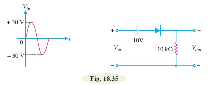
For the input wave to the clipping circuit shown in Fig. 18.35, find the output waveform.
The blue check mark means that this solution has been answered and checked by an expert. This guarantees that the final answer is accurate.
Learn more on how we answer questions.
Learn more on how we answer questions.
For any value of V_{i n}>10 \,V, the ideal diode is forward biased and V_{\text {out }}=V_{\text {in }}-10. For example, at V_{\text {in }}=15 \,V [See Fig. 18.36 (i)], V_{\text {out }}=15-10=5 \,V.
For any value of V_{\text {in }}<10 \,V, the ideal diode is reverse biased. Therefore, circuit current is zero and hence V_{\text {out }}=0. For example, with V_{\text {in }}=5 V [See Fig. 18.36 (ii)], V_{\text {out }}=0 \text { and } V_d (drop across diode) = 5 V
The output waveform will be as shown in Fig. 18.37 (ii).


Related Answered Questions
Question: 18.22
Verified Answer:
Fig. 18.65 (i) shows the output voltage waveform f...
Question: 18.21
Verified Answer:
Fig. 18.64 (i) shows the output voltage waveform f...
Question: 18.20
Verified Answer:
Fig. 18.63 (i) shows the output voltage waveform f...
Question: 18.19
Verified Answer:
During the positive half-cycle of input signal, th...
Question: 18.18
Verified Answer:
During positive half-cycle of the input signal, th...
Question: 18.17
Verified Answer:
The symmetrical zener clipper uses two zener diode...
Question: 18.16
Verified Answer:
The zener shunt clipper uses a zener diode in plac...
Question: 18.15
Verified Answer:
Fig. 18.41 shows the symmetrical clipper.
(i) Diod...
Question: 18.14
Verified Answer:
The battery of 5 V reverse biases the diode. The p...
Question: 18.13
Verified Answer:
For any value of V_{i n}>10 \,V ...