Question 11.2: Gear Tooth and Gear Mesh Parameters Two parallel shafts A an...
Gear Tooth and Gear Mesh Parameters
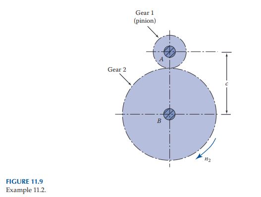
Two parallel shafts A and B with center distance c are to be connected by 2 teeth/in. diametral pitch, 20° pressure angle, and spur gears l and 2 providing a velocity ratio of r_{s} (Figure 11.9). Determine, for each gear,
a. The number of teeth N
b. The radius of the base circle r_{b} and outside diameter d_{o}
c. Clearance f
d. The pitch-line velocity V, if gear 2 rotates at speed n_{2}
Given: n_2=50 rpm , r_s=1 / 3, c=14 \text { in., } P=2 \text { in. }^{-1}, \phi=20^{\circ}
Design Decision: Common stock gear sizes are considered.
Learn more on how we answer questions.
a. Using Equation 11.6, we have r_{1} + r_{2} = c = 14 in., r_{1}/r_{2} = 1/3. Hence, r_{1} = 3.5 in., r_{2} = 10.5 in., or d_{1} = 7 in., d_{2} = 21 in. Equation 11.2 leads to
c=r_1+r_2=\frac{N_1+N_2}{2 P} (11.6)
P = \frac{N}{d} (11.2)
N_{1} = 7(2) = 14, N_{2} = 21(2) = 42
b. Base circle radii, applying Equation (11.9), are
r_b=r \cos \phi (11.9)
r_{b 1}=3.5 \cos 20^{\circ}=3.289 in .
r_{b 2}=10.5 \cos 20^{\circ}=9.867 in .
From Table 11.1, the addendum a = 1/2 = 0.5 in. Then
\begin{array}{c} d_{o 1}=7+2(0.5)=8 in . \\ d_{o 2}=21+2(0.5)=22 in . \end{array}
c. We have f = b_{d} − a. Table 11.1 gives the dedendum b_{d} = 1.25/2 = 0.625 in., and hence,
f=0.625-0.5=0.125 in
for the pinion and gear. Note as a check that from Table 11.1, f = 0.25/2 = 0.125 in.
d. Substituting the given data, Equation 11.7 results in
V=r_2 \omega_2=\frac{10.5}{12}\left(500 \times \frac{2 \pi}{60}\right)=45.81 fps
| Table 11.1 Commonly Used Standard Tooth Systems for Spur Gears |
|||
| Item | 20° Full Depth | 20° Stub | 25° Full Depth |
| Addendum a | 1/P | 0.8/P | 1/P |
| Dedendum b_{d} | 1.25/P | l/P | 1.25/P |
| Clearance f | 0.25/P | 0.2/P | 0.25/P |
| Working depth h_{k} | 2/P | 1.6/P | 2/P |
| Whole depth h | 2.25/P | 1.8/P | 2.25/P |
| Tooth thickness t | 1.571/P | 1.571/P | 1.571/P |