Question 6.4: In the frame shown, members ACE and BCD are connected by a p...
In the frame shown, members ACE and BCD are connected by a pin at C and by the link DE. For the loading shown, determine the force in link DE and the components of the force exerted at C on member BCD.

Learn more on how we answer questions.
STRATEGY: Follow the general procedure discussed in this section. First treat the entire frame as a free body, which will enable you to find the reactions at A and B. Then dismember the frame and treat each member as a free body, which will give you the equations needed to find the force at C.
MODELING and ANALYSIS: Since the external reactions involve only three unknowns, compute the reactions by considering the free-body diagram of the entire frame (Fig. 1).
+\uparrow \sum{F_y}=0: \quad \quad \quad A_y-480 \ \text{N}=0 \quad \quad A_y=+480 \text{ N} \quad \quad \pmb{\text{A}}_{y}=480 \text{ N}\uparrow \\ +\circlearrowleft \sum{M_A}=0: \quad \quad -(480 \text{ N})(100 \text{ mm})+B(160 \text{ mm})=0 \\ \quad \quad \quad \quad \quad \quad \quad \quad \quad \quad\quad \quad\quad B=+300 \text{ N} \quad \quad \pmb{\text{B}}=300 \text{ N}\longrightarrow \\ \underrightarrow{+}\sum{F_x} =0: \quad \quad B+A_x=0 \\ \quad \quad \quad \quad \quad \quad \quad \quad 300 \text{ N}+A_x=0 \quad \quad A_x=-300 \text{ N} \quad \quad \pmb{\text{A}}_x=300 \text{N}\longleftarrow
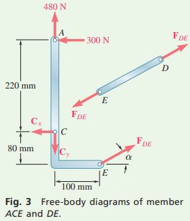
Now dismember the frame (Figs. 2 and 3). Since only two members are connected at C, the components of the unknown forces acting on ACE and BCD are, respectively, equal and opposite. Assume that link DE is in tension (Fig. 3) and exerts equal and opposite forces at D and E, directed as shown.
Free Body: Member BCD. Using the free body BCD (Fig. 2), you can write and solve three equilibrium equations:
+ \circlearrowright \Sigma M_C = 0 \\ \quad \quad(F_{DE} \sin α)(250\text{ mm}) + (300\text{ N})(80\text{ mm}) + (480\text{ N})(100\text{ mm}) = 0 \\ \quad \quad F_{DE}= -561\text{ N}\quad \quad\quad \quad\quad \quad F_{DE}= 561\text{ N} C\\ \overset{+}{\to}\Sigma Fx =0:\quad C_x – F_{DE} \cos α + 300\text{ N} = 0\\\quad \quad \quad \quad C_x – (-561\text{ N}) \cos 28.07° + 300\text{ N} = 0 \quad \quad C_x = -795\text{ N}\\ \Sigma F_y = 0:\quad C_y – F_{DE} \sin α – 480\text{ N} = 0\\ \quad \quad \quad \quad C_y – (-561\text{ N}) \sin 28.07° – 480\text{ N} = 0 \quad \quad C_y = +216\text{ N}
From the signs obtained for C_x \text{ and } C_y, the force components \pmb{\text{C}}_x \text{ and } \pmb{\text{C}}_y exerted on member BCD are directed to the left and up, respectively. Thus, you have
C_x=795 \text{ N}\longleftarrow ,C_y=216 \text{ N}\uparrow
REFLECT and THINK: Check the computations by considering the free body ACE (Fig. 3). For example,
+\circlearrowleft \sum{M_A}=(F_{DE} \cos \alpha)(300 \text{ mm})+(F_{DE} \sin \alpha)(100 \text{ mm})-C_x(220 \text{ mm}) \\ \quad \quad \quad \quad \quad =(-561 \cos \alpha)(300)+(-561 \sin \alpha)(100)-(-795)(220)=0