Question 12.4: Objective: Determine the effect of feedback on the source si...
Objective: Determine the effect of feedback on the source signal and noise signal levels.
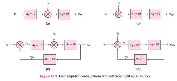
Consider the four possible amplifier configurations shown in Figure 12.3. The amplifiers are designed to provide the same output signal voltage. Determine the effect of the noise signal v_{n} .
Learn more on how we answer questions.
(Figure 12.3(a)): Two open-loop amplifiers are in a cascade configuration, and the noise signal is generated between the two amplifiers. The output voltage is
v_{oa} = A_{1} A_{2} v_{i} + A_{2} v_{n} = 100 v_{i} + 10 v_{n}
Therefore, the output signal-to-noise ratio is
\frac{S_{o}}{N_{o}} = \frac{100 v_{i}}{10 v_{n}} = 10 \frac{S_{i}}{N_{i}}
(Figure 12.3(b)): Two open-loop amplifiers are in a cascade configuration, and the noise is part of the input signal. The output voltage is
v_{ob} = A_{1} A_{2} v_{i} + A_{1} A_{2} v_{n} = 100 v_{i} + 100 v_{n}
Therefore, the output signal-to-noise ratio is
\frac{S_{o}}{N_{o}} = \frac{100 v_{i}}{100 v_{n}} = \frac{S_{i}}{N_{i}}
(Figure 12.3(c)): Two amplifiers are in a feedback configuration, and the noise signal is generated between the two amplifiers. The output voltage is
v_{oc} = A_{1} A_{2} v_{ε} + A_{2} v_{n}
and the feedback signal is
v_{f b} = β v_{o}
Then,
v_{ε} = v_{i} − v_{f b} = v_{i} − β v_{oc}
therefore,
v_{oc} = A_{1} A_{2}(v_{i} − β v_{oc}) + A_{2} v_{n}
or
v_{oc} = \frac{A_{1} A_{2}}{(1 + β A_{1} A_{2})} \cdot v_{i} + \frac{A_{2}}{(1 + β A_{1} A_{2})} \cdot v_{n} \cong 100 v_{i} + 0.1 v_{n}
The output signal-to-noise ratio is
\frac{S_{o}}{N_{o}} = \frac{100 v_{i}}{0.1 v_{n}} = 1000 \frac{S_{i}}{N_{i}}
(Figure 12.3(d)): A basic feedback configuration, and the noise is part of the input signal. The output voltage is
v_{od} = \frac{A_{1} A_{2}}{(1 + β A_{1} A_{2})} (v_{i} + v_{n}) \cong 100 v_{i} + 100 v_{n}
Therefore, the output signal-to-noise ratio is
\frac{S_{o}}{N_{o}} = \frac{100 v_{i}}{100 v_{n}} = \frac{S_{i}}{N_{i}}
Comment: Comparing the four configurations, we see that Figure 12.3(c) produces the largest output signal-to-noise ratio. This configuration may occur when amplifier A_{2} is an audio power-amplifier stage, in which large currents can produce excessive noise, and when amplifier A_{1} corresponds to a low-noise preamplifier, which provides most of the voltage gain