Question 7.4: Obtain the sequence networks for the system shown in Figure ...
Obtain the sequence networks for the system shown in Figure 7.17. Assume the following data in p.u. on the same base.
Generator G_{1}:
X_{+} = 0.2 p.u.
X_{-} = 0.12 p.u.
X_{0} = 0.06 p.u.
Generator G_{2}:
X_{+} = 0.33 p.u.
X_{-} = 0.22 p.u.
X_{0} = 0.066 p.u.
Transformer T_{1}: X_{+} = X_{-} = X_{0} = 0.2 p.u.
Transformer T_{2}: X_{+} =X_{-} = X_{0} = 0.225 p.u.
Transformer T_{3}: X_{+} = X_{-} = X_{0} = 0.27 p.u.
Transformer T_{4}: X_{+} = X_{-} = X_{0} = 0.16 p.u.
Line L_{1}: X_{+} = X_{-} = 0.14 p.u.
X_{0} = 0.3 p.u.
Line L_{2}: X_{+} = X_{-}= 0.20 p.u.
X_{0} = 0.4 p.u.
Line L_{3}: X_{+} =X_{-} = 0.15 p.u.
X_{0} = 0.2 p.u.
Load: X_{+} = X_{-} = 0.9 p.u.
X_{0} = 1.2 p.u.
Assume an unbalanced fault occurs at F. Find the equivalent sequence networks for this condition.

Learn more on how we answer questions.
The positive sequence network is as shown in Figure 7.18(A). One step in the reduction can be made, the result of which is shown in Figure 7.18(B). To avoid tedious work we utilize Thévenin’s theorem to obtain the positive sequence network in reduced form. We assign currents I_{1}, I_{2}, and I_{3} as shown in Figure 7.18(B) and proceed to solve for the open-circuit voltage between F_{+} and N_{+}.
Consider loop A. We can write
1\angle 0=j\left[0.2I_{1}+0.36\left(I_{1}- I_{3} \right)+0.9\left(I_{1}+I_{2} \right) \right]For loop B, we have
0=j\left[0.565I_{3}+0.42\left(I_{2}+ I_{3} \right)-0.36\left(I_{1}-I_{3} \right) \right]For loop C, we have
1\angle 0=j\left[0.33I_{2}+0.42\left(I_{2}+ I_{3} \right)+0.9\left(I_{1}+I_{2} \right) \right]The above three equations are rearranged to give
1\angle 0=j\left(1.46I_{1}+0.9I_{2}-0.36I_{3}\right)
0=0.36I_{1}-0.42I_{2}-1.345I_{3}
1\angle 0=j\left(0.9I_{1}+1.65I_{2}+0.42I_{3}\right)
Solving we obtain
I_{1}=- j0.4839
I_{2}=- j0.3357
I_{3}=- j0.0247
As a result, we get
V_{F_{+}N_{+} } =V_{TH} =1- j0.2I_{1}- j0.16\left(I_{1}- I_{3}\right)
=1- \left(02\right) \left(0.4839\right)- \left(0.16\right) \left(0.4839- 0.0247\right)
=0.82975
We now turn our attention to the Thévenin’s equivalent impedance, which is obtained by shorting out the sources and using network reduction. The steps are shown in Figure 7.19. As a result, we get
Z_{+}=j0.224The positive sequence equivalent is shown in Figure 7.20.
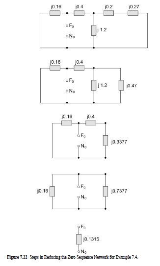
The negative sequence and zero sequence impedance networks and steps in their reduction are shown in Figure 7.21 and Figure 7.22. As a result, we get
Z_{-}=j 0.1864
Z_{0}=j0.1315