Question A8.15: Part of the control logic for an intruder alarm is shown in ...
Part of the control logic for an intruder alarm is shown in Fig. A8.31. Determine the logic required to select the Y4 output and verify that the Y3 output is permanently selected and unaffected by the states of S1 and S2.

Learn more on how we answer questions.
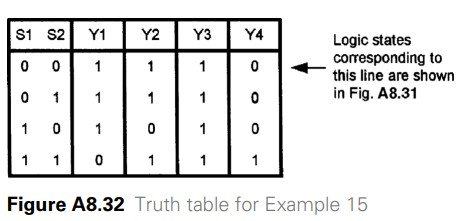
Each logic gate shown in Fig. A8.31 is a two-input NAND gate. We can construct the truth table for the control circuit (see Fig. A8.32) by placing all four possible combinations of 0 and 1 on the S1 and S2 inputs and tracing the logic states through the circuit. We have shown the first stage of this process (the logic conditions that produce the first line of the truth table) in Fig. A8.32.
From Fig. A8.32 it can be seen that the Y4 output corresponds to the AND logic function:
Y4 = S1 ⋅ S2
You can also see from Fig. A8.32 that the Y3 output remains at logic 1 regardless of the states of S1 and S2.