Question 3.14: The brass bar shown in Figure 3–7 is part of a conveyor that...
The brass bar shown in Figure 3–7 is part of a conveyor that transports components into an oven. Initially, when the temperature is 15°C, there is a total clearance of 0.25 mm between the end of the bar and the inside of the frames on both sides. Describe what happens when the temperature increases from 15°C to 90°C. Consider the frames to be rigid and that they do not change dimension as the temperature rises.

Learn more on how we answer questions.
Objective Describe the behavior of the bar as the temperature rises.
Given Initial length of bar: L = 250 mm
Initial gap: δ = 0.25 mm
Material of bar: Brass C36000, hard, α = 20.5 × 10^{-6}°C^{-1} (Table 3-4)
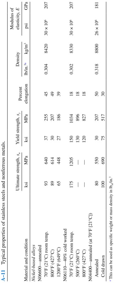
s_{y} = 310 MPa, E = 110 GPa (appendix A-11)
| TABLE 3–4 Coefficients of thermal expansion, α, for some metals, plate glass, wood, and concrete. | ||
| α | ||
| Mateial | °F^{-1} | °C^{-1} |
| Steel, SAE | ||
| 1020 | 6.5 \times 10^{-6} | 11.7 \times 10^{-6} |
| 1040 | 6.3 \times 10^{-6} | 11.3 \times 10^{-6} |
| 4140 | 6.2 \times 10^{-6} | 11.2 \times 10^{-6} |
| Structural steel | 6.5 \times 10^{-6} | 11.7 \times 10^{-6} |
| Gray cast iron | 6.0 \times 10^{-6} | 10.8 \times 10^{-6} |
| Stainless steel | ||
| SAE 301 | 9.4 \times 10^{-6} | 16.9 \times 10^{-6} |
| SAE 430 | 5.8 \times 10^{-6} | 10.4 \times 10^{-6} |
| SAE 501 | 6.2 \times 10^{-6} | 11.2 \times 10^{-6} |
| Aluminum alloys | ||
| 2014 | 12.8 \times 10^{-6} | 23.0 \times 10^{-6} |
| 6061 | 13.0 \times 10^{-6} | 23.4 \times 10^{-6} |
| 7075 | 12.9 \times 10^{-6} | 23.2 \times 10^{-6} |
| Brass, C36000 | 11.4 \times 10^{-6} | 20.5 \times 10^{-6} |
| Bronze, C22000 | 10.2 \times 10^{-6} | 18.4 \times 10^{-6} |
| Copper, CI4500 | 9.9 \times 10^{-6} | 17.8 \times 10^{-6} |
| Magnesium, ASTM AZ63 A-T6 | 14.0 \times 10^{-6} | 25.2 \times 10^{-6} |
| Titanium, Ti–6Al–4V | 5.3 \times 10^{-6} | 9.5 \times 10^{-6} |
| Plate glass | 5.0 \times 10^{-6} | 9.0 \times 10^{-6} |
| Wood (pine) | 3.0 \times 10^{-6} | 5.4 \times 10^{-6} |
| Concrete | 6.0 \times 10^{-6} | 10.8 \times 10^{-6} |
Analysis Step 1. First, determine what temperature rise will cause the bar to expand by 0.25 mm, bringing the end of the bar just into contact with the frame. Equation (3–10) can be used.
\delta = \alpha L· \Delta t
Step 2. Then, determine how much additional temperature rise occurs from that point up to when the temperature is 90°C.
Step 3. Equation (3–12) can then be used to compute the stress developed in the bar during the final temperature rise. The safety of this stress should be evaluated.
Results Step 1. The amount of temperature rise to elongate the bar 0.25 mm is
δ = αL(Δ t_{1} )
Solving for t_{1} gives
\Delta t_{1} = \frac{\delta}{ \alpha L} = \frac{0.25 mm}{(20.5 \times 10^{-6} °C^{-1})(250 mm )} = 48.8°C
Step 2. The temperature at which this occurs is
t_{2} = t_{1} + \Delta t_{1} = 15°C + 48.8°C = 63.8°C
Then, the additional temperature rise to the maximum temperature is
\Delta t_{2} = 90°C -36.8°C = 26.2°C
Step 3. For this final temperature rise, the bar is considered to be fully restrained. Therefore, a compressive stress is induced into the bar. Using Equation (3–12),
\sigma = E \alpha (\Delta t) = (110 \times 10^{9} Pa)(20.5 \times 10^{-6} °C^{-1})(26.2°C)= 59.080 MPa
Let us check this stress against yielding. Let σ = σ_{d} = s_{y}/N. Then,
N= s_{y}/ \sigma . = 310 MPa/59.08 MPa = 5.25
This is a sufficiently high design factor to ensure that yielding will not occur. However, column buckling should be checked (see Chapter 11).