Question 1.13: The cable-pipe structure ABCD shown in Fig. 1-55 has pin sup...
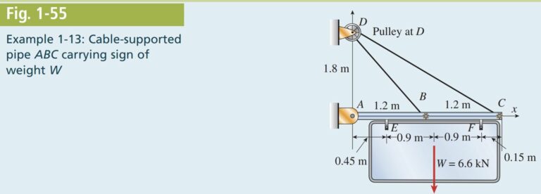
The cable-pipe structure ABCD shown in Fig. 1-55 has pin supports at points A and D, which are 1.8 m apart. Member ABC is a steel pipe, and member BDC is a continuous cable which passes over a frictionless pulley at D. A sign weighing 6.6 kN is suspended from bar ABC at points E and F.
Determine the required diameter of the pins at A, B, C, and D if the allowable stress in shear is 45 MPa. Also, find the required cross-sectional areas of bar ABC and cable BDC if the allowable stresses in tension and compression are 124 MPa and 69 MPa, respectively. (The allowable com-pression stress is lower because of the possibility of buckling instability.)
(Note: The pins at the supports are in double shear. Also, consider only the weight of the sign; disregard the weights of members BDC and ABC.)
Learn more on how we answer questions.
The first step in the overall solution is to find reaction forces at supports and the tensile force in the continuous cable BDC. These quantities are found by applying the laws of statics to free-body diagrams (see Section 1.2). Once reaction and cable forces are known, we can find the axial forces in member ABC and the shear forces in pins at A, B, C, and D. We can then find the required sizes of member ABC and the pins at A, B, C, and D.
Reactions: We begin with a free-body diagram of the entire structure (Fig. 1-56), which shows all of the applied and reaction forces. A statics sign convention is commonly used so all reaction components are initially shown in the positive coordinate directions.
Summing moments about point D (counterclockwise moments are positive) gives
Next, sum forces in the x direction:
\Sigma F_{x}=0 A_{x}+D_{x}=0 \text { or } D_{x}=-A_{x}=-4.95 \ kNThe minus sign means that D_x acts in the negative x direction.
Summing forces in the x direction at joint D will give us the force in the continuous cable BDC.
First compute angles \alpha_{B} \text { and } \alpha_{C} (see Fig. 1-56):
Now \Sigma F_{x} = 0 at joint D:
Now find the vertical reaction at joint D where T_{B}=T_{C} because the cable is one continuous cable (see Fig. 1-57).
D_{y}=T\left(\sin \left(\alpha_{B}\right)+\sin \left(\alpha_{C}\right)\right)=5.23 \ kNThe plus sign means that D_{y} acts in the positive y direction.
So, the resultant at D is
Next, sum the forces in the y direction for the entire free-body diagram to get A_{y}:
\sum F_{y}=0 \quad A_{y}+D_{y}-W=0 \text { so } A_{y}=-D_{y}+W=1.37 \ kNThe resultant at A is
A_{\text {res }}=\sqrt{A_{x}^{2}+A_{y}^{2}}=5.14 \ kNAs a final check, confirm the equilibrium using the free-body diagram of pipe ABC (see Fig. 1-58, where T_{B}=T_{C} because the cable is one continuous cable). The forces will sum to zero, and the sum of the moments about A is zero:
Determine the shear forces in pins (all are in double shear) and required diameter of each pin. Now that the reaction and cable forces are known, we
can identify the shear forces in pins at A, B, C, and D and then find the required size of each pin.
Pin at A:
Pin at B:
Pin at C:
The resultant force at C is the same as that at B, so the pin at C will have the same diameter as that at B.
Pin in pulley at D:
Determine the axial force in cable BDC and required cross-sectional area of the cable. Here we use the computed tension for T and higher allowable axial stress for members in tension:
A_{\text {cable }}=\frac{T}{\sigma_{\text {allowT }}}=\frac{3.65 \ kN }{69 \ MPa }=52.9 \ mm ^{2}Determine the axial force in pipe ABC and required cross-sectional area of the pipe. We can use free-body diagrams of portions of member ABC to
compute the axial compressive force N in segments AB and BC (as discussed in Section 1.2). For segment AB, force N_{A B} = -4.95 kN, while in segment BC, N_{B C} = -2.92 kN. The larger force N_{A B} controls. Now we must use the reduced allowable axial stress for compression, so the required area is
Notes: In this example, we intentionally omitted the self-weight of the cable–pipe structure from the calculations. However, once the sizes of the members are known, their weights can be calculated and included in the free-body diagrams given.
When the weights of the bars are included, the design of member ABC becomes more complicated. Not only because of its own weight but also because of the weight of the sign, member ABC is a beam subjected to bending and transverse shear as well as axial compression. The design of such members must wait until we study stresses in beams (Chapter 5), where a beam with axial loads is discussed as a separate topic (see Section 5.12). As the compressive forces increase, the possibility of lateral instability (or buckling) of ABC also becomes a concern; we will investigate this in Chapter 11.
In practice, other loads besides the weights of the structure and sign would have to be considered before making a final decision about the sizes of the pipes, cables, and pins. Loads that could be important include wind loads, earthquake loads, and the weights of objects that might have to be supported temporarily by the structure.
Finally, if cables BD and CD are separate cables (instead of one continuous cable as in the previous analysis where T_{B}=T_{C}), the forces T_{B} and T_{C} in the two cables are not equal in magnitude. The structure is now statically indeterminate, and the cable forces and the reactions at A cannot be deter-mined using the equations of static equilibrium alone. We will consider problems of this type in Chapter 2, Section 2.4 (see Example 2-5).


