Question 10.3: The horizontal shaft AD is attached to a fixed base at D and...
The horizontal shaft AD is attached to a fixed base at D and is subjected to the torques shown. A 44-mm-diameter hole has been drilled into portion CD of the shaft. Knowing that the entire shaft is made of steel for which G = 77 GPa, determine the angle of twist at end A.

Learn more on how we answer questions.
STRATEGY: Use free-body diagrams to determine the torque in each shaft segment AB, BC, and CD. Then use Eq. (10.16) to determine the angle of twist at end A.
\phi=\sum\limits_{i}{\frac{T_iL_i}{J_iG_i} } \quad \quad \quad \quad \pmb{(10.16)}
MODELING:
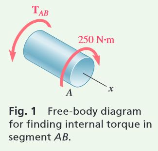
Passing a section through the shaft between A and B (Fig. 1), we find
Passing now a section between B and C (Fig. 2) we have
\sum M_x=0: \ \ (250 \text{ N.m})+(2000 \text{ N.m})-T_{BC}=0 \quad \quad T_{BC}=2250 \text{ N.m}Since no torque is applied at C,
T_{CD}=T_{BC}=2250 \text{ N.m}
ANALYSIS:
Polar of Moments of Inertia.
Using Fig. 3
J_{AB}=\frac{\pi}{2}c^4=\frac{\pi}{2}(0.015 \text{ m})^4=0.0795 \times 10^{-6} \text{ m}^4 \\ J_{BC}=\frac{\pi}{2}c^4 =\frac{\pi}{2}(0.030 \text{ m})^4 =1.272 \times 10^{-6}\text{ m} ^4 \\ J_{CD}=\frac{\pi}{2} (c_2^4-c_1^4)=\frac{\pi}{2}[(0.030 \text{ m})^4-(0.022 \text{ m})^4] =0.904 \times 10^{-6} \text{ m}^4
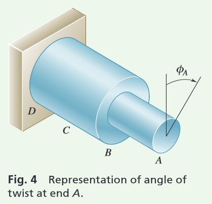
Angle of Twist. From Fig. 4, using Eq. (10.16) and recalling that G = 77 GPa for the entire shaft, we have
\phi_A=\sum_i \frac{T_iL_i}{J_iG}=\frac{1}{G}\left(\frac{T_{AB}L_{AB}}{J_{AB}}+\frac{T_{BC}L_{BC}}{J_{BC}}+\frac{T_{CD}L_{CD}}{J_{CD}} \right) \\ \phi_A=\frac{1}{77 \text{ GPa}}\left[\frac{(250 \text{ N.m})(0.4 \text{ m})}{0.0795 \times 10^{-6} \text{ m}^4}+\frac{(2250)(0.2)}{1.272 \times 10^{-6}} +\frac{(2250)(0.6)}{0.904 \times 10^{-6}} \right] \\ \quad =0.01634+0.00459+0.01939=0.0403 \text{ rad} \\ \phi_A=(0.0403 \ \text{rad})\frac{360 ^\circ}{2 \pi \ \text{rad}} \quad \quad \quad \quad \quad \quad \quad \quad \phi_A=2.31 ^\circ