Goal We are to find the forces acting on the pins at A and G.
Given We are given information about the geometry of the backhoe, and the load at L.
Assume Treat the system as planar because all the forces are acting in a single plane. We also assume that all of the hydraulic cylinders act as two-force members because they are pinned at both ends and have no other external forces acting on them.
Draw, Formulate Equations and Solve We draw an imaginary boundary around the whole backhoe arm, which isolates it from the cab at A and J. We draw a free-body diagram of the arm (Figure 2) realizing that since hydraulic cylinder JK is a two-force member, the unknown force at J must act along the axis of the member. We represent the unknown force at the pin connection A by two mutually perpendicular forces (see Table 4.1). Note that there are three unknown forces on this free-body diagram, including the unknown load at A that we are looking for.
We set up the equations for planar equilibrium to find the unknown load at A.
based on the free-body diagram in Figure 2, we write:
\sum{M_{z @ A} }\left(\curvearrowleft + \right) = – F_{JK} (1.2 m) – 14.0 kN(1.3 m) =0
F_{JK}=-14.0 kN\left\lgroup\frac{1.3 m}{1.2 m} \right\rgroup =- 15.2 kN
The negative sign indicates that the force at J is acting in the opposite direction from our free-body diagram, meaning that the hydraulic cylinder is actually in tension. Now writing the force equilibrium equations:
\sum{F_{x} \left(\rightarrow + \right) } =-14.0 kN+ F_{Ax} = 0\Rightarrow F_{Ax}= 14.0 kN
\sum{F_{y}\left(\uparrow + \right) } = F_{JK}+F_{Ay} =0\Rightarrow F_{Ay}= -F_{JK}= 15.2 kN
Now we have all of the information to find the magnitude of F_{A} (the force acting on the pin at A):
\left\|F_{A}\right\| =\left(F^{2}_{Ax}+ F^{2}_{Ay} \right) ^{1/2}=\left[\left(14.0 kN\right) ^{2} + \left(15.2 kN\right) ^{2}\right]^{1/2}
\left\|F_{A}\right\| =20.7 kN
The orientation angle α of F_{A} (Figure 3) is given by
\alpha = \tan ^{-1} \left\lgroup\frac{15.2 kN}{14.0 kN} \right\rgroup = 47.4 ^{\circ }
Alternately, we could give the answer in vector notation as F_{A} = 14.0 kNi + 15.2 kNj, or in terms of space angles as
\left\|F_{A}\right\| = 20.7 kN , \theta _{x} = 47.4°, \theta _{y} = 42.6°, \theta _{z} = 90°.
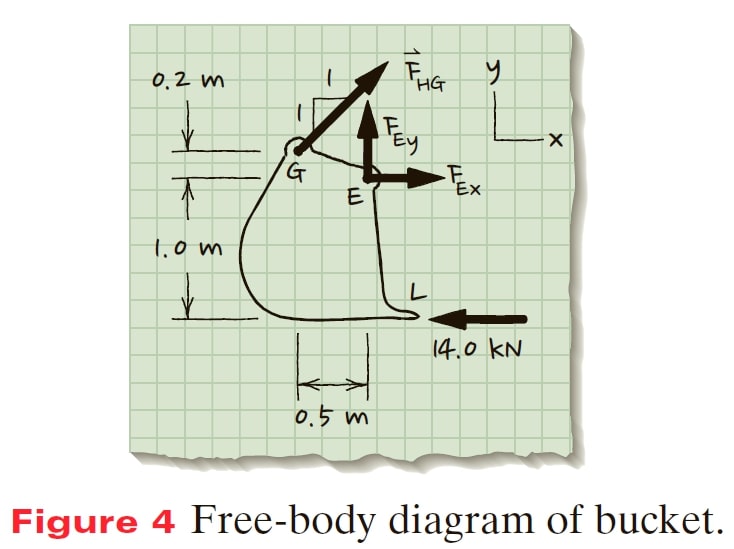
Draw, Formulate Equations and Solve Now we consider the bucket in order to find the force acting at pin G. We isolate the bucket and draw a free-body diagram (Figure 4). using the free-body diagram drawn in Figure 4, we set up the equations for planar equilibrium to find the load acting on hydraulic cylinder HG.
\sum{M_{z @ E} }=0\left(\curvearrowleft + \right)
– F_{HG}\cos 45^{\circ }(0.2 m)- F_{HG}\sin 45^{\circ } (0.5 m) − 14.0 kN(1.0 m) = 0
F_{HG}= -14.0 kN\left\lgroup\frac{1.0 m}{0.495 m} \right\rgroup \Rightarrow F_{HG}=-28.3 kN
The negative sign for the F_{HG} indicates that the force is acting in the opposite direction from that on the free-body diagram so the hydraulic cylinder is in compression.
Check It is useful to redraw the free-body diagram with the values of the loads at the supports (Figure 5); this shows us that the couple created by the vertical forces at J and A is balanced by the couple created by the horizontal forces at L and A.
Table 4.1 Standard Supports for Planar Systems
| (A) Supports |
Description of Loads | (B) Loads to Be Shown on Free-Body Diagram |
| 1. Normal contact without friction
|
Force (F) oriented normal to surface on which system rests. Direction is such that force pushes on system. | F
|
| 2. Cable, rope, wire
|
Force (F) oriented along cable. Direction is such that cable pulls on the system. | F
|
| 3. Link
|
Force (F) oriented along link length; F force can push or pull on the system. | F
|
| 4. Spring
|
Force (F) oriented along long axis of spring. Direction is such that spring pulls on system if spring is in tension, and pushes if spring is in compression. | F
|
| 5. Slot-on-pin (frictionless)
|
Force (F) oriented normal to long axis of slot. Direction is such that force can pull or push on system. The slot is frictionless. Therefore no forces act parallel to the slot. | F
|
| 6. Pin-in-slot (frictionless)
|
Force (F) oriented normal to long axis of slot. Direction is such that force can pull or push on system. The slot is frictionless. Therefore no forces act parallel to the slot. | F
|
| 7. Roller or rocker
|
Force (F) oriented normal to surface on which system rests. Direction is such that force pushes on system. | F
|
| 8. Normal contact with friction
|
Two force components, one ( F_y ) , oriented normal to surface on which the system rests so as to push on system, other force ( F_x ) is tangent to surface. | F_y , F_x
|
| 9. Pin connection
|
Force perpendicular to pin axis represented in terms of components F_x and F_y . Point of application is at center of pin. Alternative representation: Force (F) oriented at angle θ with respect to coordinate system. Point of application is at center of pin. |
F_x , F_y F,θ
|
| 10. Fixed sup
|
Force in x-y plane represented in terms of components F_x and F_y .Moment about z axis (M_{z}). Alternative representation: Force (F) oriented at angle θ with respect to coordinate system. Moment about z axis ( M_z ). |
F_x , F_y , M_z F, θ, M_z
|
| 11. Smooth collar on smooth shaft
|
Force (F) oriented perpendicular to long axis of shaft. Direction is such that force can pull or push on system. Moment ( M_z ) about z axis. | F, M_z
|


 port
port