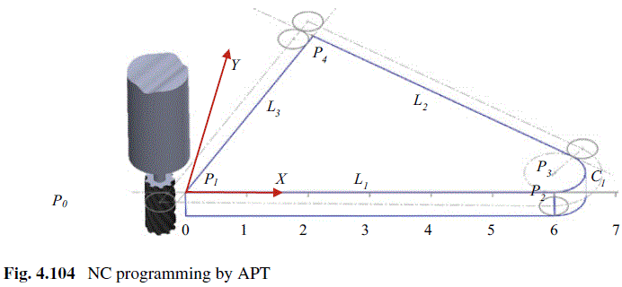
Question 4.9: Use APT to write a NC program to mill the part shown in Fig....
Use APT to write a NC program to mill the part shown in Fig. 4.104

The blue check mark means that this solution has been answered and checked by an expert. This guarantees that the final answer is accurate.
Learn more on how we answer questions.
Learn more on how we answer questions.
By using APT, the NC program is written and shown in Table 4.11. The first part (line 1–3) is to label the program, specify machining type, and select the tool. The second part (line 4–13) is to define all geometric entities. The third part (line 14–16) is to set up operating conditions for cutting speed, feed rate, and coolant supply. The fourth part (line 17–22) is for all motion statements. The last part (line 24–26) is to reset the tool position and terminate the machining operation.
Table 4.11 NC program to mill the part in Fig. 4.103
| NC Code | Explanation | |
| Line 1: | PARTNO / EXAMPLE9-3 | ; label the program as “EXAMLE9-4” |
| Line 2: | MACHIN / MILL, 1 | ; select the target machine and controller type |
| Line 3: | CUTTER/ 0.5000 | ; specifies the cutter diameter |
| Line 4: | P0=POINT/-1.0, -1.0, 0.0 | ; geometry statement to specify the pertinent surface of part |
| Line 5: | P1=POINT/ 0.0, 0.0, 0.0 | |
| Line 6: | P2=POINT/ 6.0, 0.0, 0.0 | |
| Line 7: | P3=POINT/ 6.0, 1.0, 0.0 | |
| Line 8: | P4=POINT/ 2.0, 4.0, 0.0 | |
| Line 9: | L1=LINE/P1, P2 | |
| Line 10: | C1=CIRCLE/CENTER, P3, RADIUS, 1.0 | |
| Line 11: | L2=LINE/P4, LEFT, TANTO, C1 | |
| Line 12: | L3=LINE/P1, P4 | |
| Line 13: | PL1=PLANE/P1, P2, P3 | |
| Line 14: | SPINDLE/573 | ; set the spindle speed to 573 RPM |
| Line 15: | FEDRAT/5.39 | ; set the feed rate to 5.39 inch per minute |
| Line 16: | COOLNT/ON | ; turn the coolant on |
| Line 17: | FROM/P0 | ; gives the starting position for the tool |
| Line 18: | GO/PAST, L3, TO, PL1, TO, L1 | ; initialize motion, drive, part, and check surfaces |
| Line 19: | GOUP/L3, PAST, L2 | ; contour the part in clockwise direction |
| Line 20: | GORGT/L2, TANTO, C1 | |
| Line 21: | GOFWD/C1, ON, P2 | |
| Line 22: | GOFWD/L1, PAST, L3 | |
| Line 23: | RAPID | ; move rapidly once cutting is down |
| Line 24: | GOTO/P0 | ; return the tool to home position |
| Line 25: | COOLNT/OFF | ; turn off the coolant |
| Line 26: | FINI | ; terminate the program |

Related Answered Questions
Question: 4.10
Verified Answer:
The milling operation is to create the profile of ...
Question: 4.8
Verified Answer:
The incremental coordinates of a new working point...
Question: 4.7
Verified Answer:
The absolute coordinates are measured from origin ...
Question: 4.6
Verified Answer:
Based on the provided information, the workpiece a...
Question: 4.5
Verified Answer:
Firstly, the part is modeled based on the dimensio...
Question: 4.4
Verified Answer:
Firstly, the basic size is used to locate the roww...
Question: 4.3
Verified Answer:
Equation (4.10) is used to evaluate the maximum an...
Question: 4.2
Verified Answer:
For the baseline dimensioning in Fig. 4.33a, the d...
Question: 4.1
Verified Answer:
The Solidwork Simulation is used to analyze a comp...