Question 12.9: Voltage Supply Limits in an Inverting Amplifier Compute and ...
Voltage Supply Limits in an Inverting Amplifier
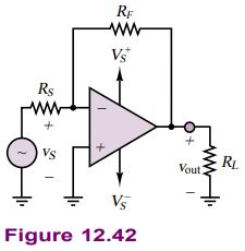
Compute and sketch the output voltage of the inverting amplifier of Figure 12.42.
Learn more on how we answer questions.
Known Quantities: Resistor and supply voltage values; input voltage.
Find: v_{\text {out }}(t).
Schematics, Diagrams, Circuits, and Given Data: R_{S}=1 \mathrm{k} \Omega ; R_{F}=10 \mathrm{k} \Omega ; R_{L}=1 \mathrm{k} \Omega ; V_{S}^{+}=15 \mathrm{~V} ; V_{S}^{-}=-15 \mathrm{~V} ; v_{S}(t)=2 \sin (1,000 t).
Assumptions: Assume supply voltage-limited op-amp.
Analysis: For an ideal op-amp the output would be:
v_{\text {out }}(t)=-\frac{R_{F}}{R_{S}} v_{S}(t)=-10 \times 2 \sin (1,000 t)=-20 \sin (1,000 t)
However, the supply voltage is limited to \pm 15 \mathrm{~V}, and the op-amp output voltage will therefore saturate before reaching the theoretical peak output value of \pm 20 \mathrm{~V}. Figure 12.43 depicts the output voltage waveform.
Comments: In a practical op-amp, saturation would be reached at 1.5 \mathrm{~V} below the supply voltages, or at approximately \pm 13.5 \mathrm{~V}.
Focus on Computer-Aided Solutions: An Electronics Workbench { }^{\mathrm{TM}} simulation of the circuit of Figure 12.42 can be found in the accompanying CD-ROM.
