\text { Given } \quad k W=5 \quad n=720 rpm \quad \alpha=20^{\circ} \quad z_{1}=2 .
z_{2}=40 \text { teeth } \quad q=10 \quad m=5 mm .
Step I Components of tooth force acting on worm
d_{1}=q m=10(5)=50 mm .
\tan \gamma=\frac{z_{1}}{q}=\frac{2}{10}=0.2 \quad \text { or } \quad \gamma=11.31^{\circ} .
M_{t}=\frac{60 \times 10^{6}( kW )}{2 \pi n_{1}}=\frac{60 \times 10^{6}(5)}{2 \pi(720)} .
=66314.56 N – mm .
\left(P_{1}\right)_{t}=\frac{2 M_{t}}{d_{1}}=\frac{2(66314.56)}{50}=2653 N .
V_{s}=\frac{\pi d_{1} n_{1}}{60000 \cos \gamma}=\frac{\pi(50)(720)}{60000 \cos (11.31)} .
= 1.92 m/s.
From Fig. 20.9, the coefficient of friction is 0.035.
From Eqs (20.30),
\left(P_{1}\right)_{a}=\left(P_{1}\right)_{t} \times \frac{(\cos \alpha \cos \gamma-\mu \sin \gamma)}{(\cos \alpha \sin \gamma+\mu \cos \gamma)} (20.30).
\left(P_{1}\right)_{a}=\left(P_{1}\right)_{t} \times \frac{(\cos \alpha \cos \gamma-\mu \sin \gamma)}{(\cos \alpha \sin \gamma+\mu \cos \gamma)} .
=(2653) \frac{[\cos (20) \cos (11.31)-0.035 \sin (11.31)]}{[\cos (20) \sin (11.31)+0.035 \cos (11.31)]} .
= 11097 N.
From Eq. (20.31),
\left(P_{1}\right)_{r}=\left(P_{1}\right)_{t} \times \frac{\sin \alpha}{(\cos \alpha \sin \gamma+\mu \cos \gamma)} (20.31),
\left(P_{1}\right)_{r}=\left(P_{1}\right)_{t} \times \frac{\sin \alpha}{(\cos \alpha \sin \gamma+\mu \cos \gamma)} .
=(2653) \frac{\sin (20)}{[\cos (20) \sin (11.31)+0.035 \cos (11.31)]} .
= 4150 N.
Step II Components of tooth force acting on worm wheel
The force components acting on the worm wheel are as follows (Eqs 20.22 to 20.24):
\left(P_{2}\right)_{t}=\left(P_{1}\right)_{a} . (20.22)
\left(P_{2}\right)_{a}=\left(P_{1}\right)_{t} . (20.23)
\left(P_{2}\right)_{r}=\left(P_{1}\right)_{r} . (20.24)
\left(P_{2}\right)_{t}=\left(P_{1}\right)_{a}=11097 N .
\left(P_{2}\right)_{a}=\left(P_{1}\right)_{t}=2653 N .
\left(P_{2}\right)_{r}=\left(P_{1}\right)_{r}=4150 N .
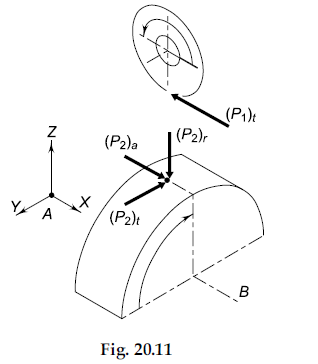
The directions of the three components is decided with reference to Fig. 20.11.
(i) Tangential Component \left(P_{2}\right)_{t} The worm has right-hand threads and when the right-hand thumb rule is applied by keeping the fingers in the direction of rotation, the thumb will be projecting along the positive Y-axis. Therefore, if we treat the worm as a ‘screw’ and the worm wheel as ‘nut’, the screw will have a tendency to move in the direction of the thumb or along the positive Y-axis. The nut or the worm wheel will have a tendency to move in the opposite direction, i.e., along the negative Y-axis.
Therefore, the worm wheel will rotate in the clockwise direction when observed from the bearing B. The worm wheel is the driven member and the direction of \left(P_{2}\right)_{t} will be the same as the direction of rotation or along the negative Y-axis.
(ii) Axial Component \left(P_{2}\right)_{a} The worm is the driving element. It is rotating in an anti-clockwise direction as shown in the figure. The direction of tangential component for the driving element is opposite to the direction of rotation. Therefore, \left(P_{1}\right)_{t} will act in the negative X-direction. Since \left(P_{1}\right)_{t} \text { and }\left(P_{2}\right)_{a} are equal and opposite, the direction of \left(P_{2}\right)_{a} a will be along the positive X-direction.
(iii) Radial Component \left(P_{2}\right)_{r} The radial component always acts towards the centre of gear. Therefore, \left(P_{2}\right)_{r} will act towards the centre of worm wheel or along negative Z-direction.
Step III Reactions at two bearings
The forces acting on the worm wheel shaft are shown in Fig. 20.12. For the sake of convenience, we will call the XZ plane as the vertical plane and the XY plane as the horizontal plane. The forces in the vertical and horizontal planes are shown in Fig. 20.13.
Taking moment of forces in the vertical plane about the bearing A,
4150 \times 60+2653 \times 100=\left(R_{B}\right)_{v} \times 120 .
\left(R_{B}\right)_{v}=4285.83 N .
Considering equilibrium of vertical forces,
\left(R_{A}\right)_{v}+4150=4285.83 .
\left(R_{A}\right)_{v}=135.83 N .
Considering forces in the horizontal plane,
\left(R_{A}\right)_{h}=\left(R_{B}\right)_{h}=11097 / 2=5548.5 N .
Considering equilibrium of axial forces,
\left(R_{B}\right)_{a}=2653 N .