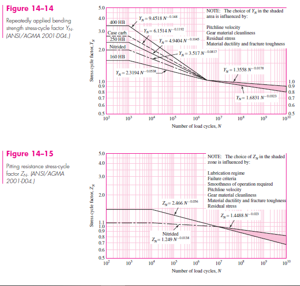
A 17-tooth 20° normal pitch-angle helical pinion with a right-hand helix angle of 30° rotates at 1800 rev/min when transmitting 4 hp to a 52-tooth helical gear. The normal diametral pitch is 10 teeth/in, the face width is 1.5 in, and the set has a quality number of 6. The gears are straddle-mounted with bearings immediately adjacent. The pinion and gear are made from a through-hardened steel with surface and core hardnesses of 240 Brinell on the pinion and surface and core hardnesses of 200 Brinell on the gear. The transmission is smooth, connecting an electric motor and a centrifugal pump. Assume a pinion life of 10^{8} cycles and a reliability of 0.9 and use the upper curves in Figs. 14–14 and 14–15.
(a) Find the factors of safety of the gears in bending.
(b) Find the factors of safety of the gears in wear.
(c) By examining the factors of safety identify the threat to each gear and to the mesh.
Question 14.5: A 17-tooth 20° normal pitch-angle helical pinion with a righ...
Learn more on how we answer questions.
ll of the parameters in this example are the same as in Ex. 14–4 with the exception that we are using helical gears. Thus, several terms will be the same as Ex. 14–4. The reader should verify that the following terms remain unchanged: K_{o} = 1, Y_{P} = 0.303, Y_{G} = 0.412, m_{G} = 3.059, (K_{s})_{P} = 1.043, (K_{s})_{G} = 1.052, (Y_{N} )_{P} = 0.977, (Y_N )_G = 0.996, K_R = 0.85, K_T = 1, C_f = 1, C_p = 2300 \sqrt{psi}, (S_t )_P = 31 350 psi, (S_{t} )_{G} = 28 260 psi, (S_{c})_{P} = 106 380 psi, (S_{c})_{G} = 93 500 psi, (Z_{N} )_{P} = 0.948, (Z_{N} )_{G} = 0.973, and C_{H} = 1.005.
For helical gears, the transverse diametral pitch, given by Eq. (13–18), is
P_n = \frac{P_t}{ \cos ψ} (13–18)
P_{t} = P_{n} \cos ψ = 10 cos 30° = 8.660 teeth/in
Thus, the pitch diameters are d_{P} = N_{P}/P_{t} = 17/8.660 = 1.963 in and d_{G} = 52/8.660 =6.005 in. The pitch-line velocity and transmitted force are
V =\frac{πd_{P}n_{P}}{12} =\frac{π(1.963)1800}{12} = 925 ft/min
W^{t} =\frac{33 000H}{V} =\frac{33 000(4)}{925} = 142.7 lbf
As in Ex. 14–4, for the dynamic factor, B = 0.8255 and A = 59.77. Thus, Eq. (14–27) gives
K_{v} =\begin{cases} \left(\frac{A + \sqrt{V}}{A}\right)^{B} & V in ft/min\\ \left(\frac{A + \sqrt{200V}}{A}\right)^{B}&V in m/s\end{cases} (14-27)
K_{v} =\left( \frac{59.77 + \sqrt{925}}{59.77}\right)^{0.8255}= 1.404
The geometry factor I for helical gears requires a little work. First, the transverse pressure angle is given by Eq. (13–19)
cos ψ =\frac{tan \phi_{n}}{tan phi_{t}} (13–19)
\phi_{t} = tan^{−1} \left(\frac{tan \phi_{n} }{cos ψ}\right)
=tan^{−1} \left(\frac{tan 20°}{cos 30°}\right)= 22.80°
The radii of the pinion and gear are r_{P} = 1.963/2 = 0.9815 in and r_{G} = 6.004/2 = 3.002 in, respectively. The addendum is a = 1/P_{n} = 1/10 = 0.1, and the base-circl radii of the pinion and gear are given by Eq. (13–6) with \phi = \phi_{t} :
r_{b} = r cos \phi (13–6)
(r_{b})_{P} = r_{P} cos \phi_{t} = 0.9815 cos 22.80° = 0.9048 in
(r_{b})_{G} = 3.002 cos 22.80°= 2.767 in
From Eq. (14–25), the surface strength geometry factor
Z =\left[ (r_{P} + a)^{2} − r^{2}_{bP}\right]^{1/2}+\left[(r_{G} + a)^{2} − r^{2}_{bG}\right]^{1/2}− (r_{P} + r_{G}) sin \phi_{t} (14–25)
Z =\sqrt{(0.9815 + 0.1)^{2} − 0.9048^{2}} +\sqrt{(3.004 + 0.1)^{2} − 2.769^{2}}− (0.9815 + 3.004) sin 22.80°
= 0.5924 + 1.4027 − 1.544 4 = 0.4507 in
Since the first two terms are less than 1.544 4, the equation for Z stands. From Eq. (14–24) the normal circular pitch p_{N} is
p_{N} = p_{n} cos \phi_{n} (14–24)
p_{N} = p_{n} cos \phi_{n} =\frac{π}{P_{n}} cos 20° =\frac{π}{10}cos 20° = 0.2952 in
From Eq. (14–21), the load sharing ratio
m_{N} =\frac{p_{N}}{0.95Z} (14–21)
m_{N} =\frac{p_{N}}{0.95Z}=\frac{0.2952}{0.95(0.4507)} = 0.6895
Substituting in Eq. (14–23), the geometry factor I is
I =\begin{cases} \frac{cos \phi_{t} sin \phi_{t}}{2m_{N}}{m_{G}}{m_{G} + 1} & external gears \\ \frac{cos \phi_{t} sin \phi_{t}}{2m_{N}}{m_{G}}{m_{G} – 1}& internal gears \end{cases} (14.23)
I =\frac{sin 22.80° cos 22.80°}{2(0.6895)}{3.06}{3.06 + 1 }=0.195
From Fig. 14–7, geometry factors J^{′}_{P} = 0.45 and J^{′}_{G} = 0.54. Also from Fig. 14–8 the J-factor multipliers are 0.94 and 0.98, correcting J^{′}_{P} and J^{′}_{G} to
J_{P} = 0.45(0.94) = 0.423
J_{G} = 0.54(0.98) = 0.529
The load-distribution factor K_{m} is estimated from Eq. (14–32):
C_{p f} =\begin{cases} \frac{F}{10d} − 0.025 & F ≤ 1 in \\ \frac{F}{10d} − 0.0375 + 0.0125F & 1 < F ≤ 17 in\\ \frac{F}{10d} − 0.1109 + 0.0207F − 0.000 228F^{2}&17 < F ≤ 40 in \end{cases} (14-32)
C_{p f} =\frac{1.5}{10(1.963)} − 0.0375 + 0.0125(1.5) = 0.0577
with C_{mc} = 1, C_{pm} = 1, C_{ma} = 0.15 from Fig. 14–11, and C_{e} = 1. Therefore, from Eq. (14–30),
K_{m} = C_{mf} = 1 + C_{mc}(C_{p f} C_{pm} + C_{ma}C_{e}) (14–30)
K_{m}= 1 + (1)[0.0577(1) + 0.15(1)] = 1.208
(a) Pinion tooth bending. Substituting the appropriate terms into Eq. (14–15) using P_{t} gives
σ =\begin{cases} W^{t} K_{o}K_{v}K_{s} \frac{P_{d}}{F}\frac{K_{m}K_{B}}{J} & (U.S. customary units)\\ W^{t} K_{o}K_{v}K_{s} \frac{1}{bm_{t}}\frac{K_{H} K_{B}}{Y_{J}} & (SI units) \end{cases} (14-15)
(σ )_{P} =\left( W^{t} K_{o}K_{v}K_{s} \frac{P_{t}}{F} \frac{K_{m}K_{B}}{J}\right)_{P} =142.7(1)1.404(1.043) \frac{8.66}{1.5} \frac{1.208(1)}{0.423}
= 3445 psi
Substituting the appropriate terms for the pinion into Eq. (14–41) gives
S_{F} =\frac{S_{t}Y_{N} /(K_{T} K_{R})}{σ} =\frac{fully corrected bending strength}{bending stress} (14–41)
(S_{F} )_{P} =\left(\frac{S_{t}Y_{N} /(K_{T} K_{R})}{σ}\right)_{P} =\frac{31 350(0.977)/[1(0.85)]}{3445} = 10.5Gear tooth bending. Substituting the appropriate terms for the gear into Eq. (14–15) gives
(σ )_{G}=142.7(1)1.404(1.052) \frac{8.66}{1.5} \frac{1.208(1)}{0.529}= 2779 psi
Substituting the appropriate terms for the gear into Eq. (14–41) gives
(S_{F} )_{G} =\frac{28 260(0.996)/[1(0.85)]}{2779} = 11.9
(b) Pinion tooth wear. Substituting the appropriate terms for the pinion into Eq. (14–16) gives
σ_{c} =\begin{cases} C_{p} \sqrt{ W^{t} K_{o}K_{v}K_{s} \frac{K_{m}}{d_{P F}} \frac{C_{f}}{I}} & (U.S. customary units) \\ C_{p} \sqrt{ W^{t} K_{o}K_{v}K_{s} \frac{K_{H}}{d_{w1}b} \frac{Z_{R}}{Z_{I}}}& (SI units) \end{cases} (14-16)
(σ_{c})_{P} = C_{p} \left(W^{t} K_{o}K_{v}K_{s} \frac{K_{m}}{d_{P} F} \frac{C_{f}}{I}\right)^{1/2}_{P}
= 2300\left[ 142.7(1)1.404(1.043)\frac{1.208}{1.963(1.5)} \frac{1}{0.195}\right]^{1/2}= 48 230 psi
Substituting the appropriate terms for the pinion into Eq. (14–42) gives
S_{H} =\frac{S_{c}Z_{N}C_{H}/(K_{T} K_{R})}{σ_{c}} =\frac{fully corrected contact strength}{contact stress} (14–42)
(S_{H})_{P} =\left[ \frac{S_{c}Z_{N} /(K_{T} K_{R})}{σ_{c}}\right]_{P} =\frac{106 400(0.948)/[1(0.85)]}{48 230} = 2.46
Gear tooth wear. The only term in Eq. (14–16) that changes for the gear is Ks. Thus,
(σ_{c})_{G} =\left[\frac{(K_{s})_{G}}{(K_{s})_{P}}\right]^{1/2} (σ_{c})_{P} =\left(\frac{1.052}{1.043}\right)^{1/2} 48 230 = 48 440 psi
Substituting the appropriate terms for the gear into Eq. (14–42) with C_{H} = 1.005 gives
(S_{H})_{G} =\frac{93 500(0.973)1.005/[1(0.85)]}{48 440} =2.22
(c) For the pinion we compare S_{F} with S^{2}_{H}, or 10.5 with 2.46^2 = 6.05 , so the threat in the pinion is from wear. For the gear we compare S_{F} with S^{2}_{H}, or 11.9 with 2.22^{2} = 4.93, so the threat is also from wear in the gear. For the meshing gearset wear controls.

