(a) Determine the unloaded output voltage of the voltage divider in Figure 7-30.
(b) Find the loaded output voltages of the voltage divider in Figure 7-30 for the following two values of load resistance: RL = 10 kΩ and RL = 100 kΩ.
(a) Determine the unloaded output voltage of the voltage divider in Figure 7-30.
(b) Find the loaded output voltages of the voltage divider in Figure 7-30 for the following two values of load resistance: RL = 10 kΩ and RL = 100 kΩ.

(a) The unloaded output voltage is
VOUT(unloaded)=(R1+R2R2)VS=(14.7 kΩ10 kΩ)5 V=3.40 V(b) With the 10 kΩ load resistor connected, RL is in parallel with R2 which gives
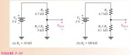
R2∥RL=R2+RLR2RL=20 kΩ100 MΩ=5 KΩThe equivalent circuit is shown in Figure 7-31 (a). The loaded output voltage is
VOUT(loaded)=(R1+R2∣∣RLR2∣∣RL)VS=(9.7 kΩ5 kΩ)5 V=2.58 VWith the 100 kΩ load, the resistance from output to ground is
R2∥RL=R2+RLR2RL=110 kΩ(10 kΩ)(100 kΩ)=9.1 KΩThe equivalent circuit is shown in Figure 7-31(b). The loaded output voltage is
VOUT(loaded)=(R1+R2∣∣RLR2∣∣RL)VS=(13.8 kΩ9.1 kΩ)5 V=3.30 VFor the smaller value of RL, the reduction in VOUT is
3.40 V — 2.58 V = 0.82 V (a 24% drop in output voltage)
For the larger value of RL, the reduction in VOUT is
3.40 V – 3.30 V = 0.10 V (a 3% drop in output voltage)
This illustrates the loading effect of RL, on the voltage divider.