(A) Draw the transfer characteristics of the circuit of figure, assuming both D_{1} \text { and } D_{2} to be ideal (B) How would the characteristics change if D_{2} is ideal, but D_{1} is no-ideal and has a forward resistance of 10 W and a reverse of infinity.
Share
Share
Question 2.1: (A) Draw the transfer characteristics of the circuit of figu...

The Blue Check Mark means that this solution has been answered and checked by an expert. This guarantees that the final answer is accurate.
Learn more on how we answer questions.
Learn more on how we answer questions.
(A) Both the Diodes are ideal whom V_{0} is between 1V to 2V 1 V \leq V _{0} \leq 2 V in this case both the diodes D_{1} \text { and } D_{2} are forward bias
1 V and 2 V can not be in parallel and its violation of KVL
So this circuit does not exist.
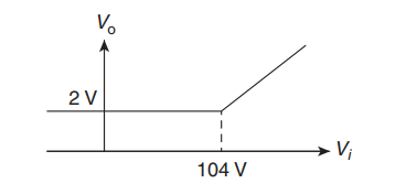
\text { (B) } V_{0} \leq 2 V \left(D_{2} f, B \text { and } D_{1} f, B\right)Apply KCL
\begin{aligned}&I+I_{1}=I_{2}+I_{3} \\&\frac{V_{i}-2}{1 k}+I_{1}=\frac{2-1}{10}+\frac{2-0}{1 k} \\&i_{1}=\frac{104-V_{i}}{1000} \\&i \geq 0 \\&\begin{aligned}\frac{104-V_{i}}{1000} & \geq 0 \\V_{i} & \leq 104 \\V_{i} & \leq 104 V \Rightarrow V_{0}=2 V\end{aligned}\end{aligned}Case 2: V_{i} \geq 104 V \text {, so } V_{0} \geq 2 V \text { Diode } D_{1} is forward bias Diode D_{2} is reverse bias
Apply KCL
\begin{aligned}\frac{V_{0}-V_{i}}{1 K}+\frac{V_{0}-1}{10}+\frac{V_{0}-0}{1 K} &=0 \\V_{0} &=\frac{V_{i}+100}{102}\end{aligned}


Related Answered Questions
Half wave rectifier is given as
y = x for x ≥ 0
= ...
\vec{E}=24 e^{j(\omega t-\beta z)} \vec{a}_...
\begin{aligned}&\eta_{1}=\sqrt{\frac{\m...
\theta BBrewster angle,
\beg...
Wave is travelling in +z direction.
\begin{...
Fig.1 D N_{1}-D N_{2}=P_{S}
...
Given, E_{y}=10 e^{j(\omega t-\beta z)}[/l...
\begin{aligned}&\vec{E}=E_{0}^{J(\omega...
\mu_{ r }=1, E_{r}=4.
\begin...
Total internal inflection takes place when inciden...