A pipe with an outside diameter of 140 mm and a wall thickness of 7 mm is subjected to the 16-kN load shown in Figure P15.79. The internal pressure in the pipe is 2.50 MPa, and the yield strength of the steel is \sigma_{Y} = 240 MPa.
(a) Determine the factors of safety predicted at points H and K by the maximum-shear-stress theory of failure.
(b) Determine the Mises equivalent stresses at points H and K.
(c) Determine the factors of safety at points H and K predicted by the maximum-distortion-energy theory.

Section properties:
\begin{aligned}&d=140 mm -2(7 mm )=126 mm \\&A=\frac{\pi}{4}\left[(140 mm )^{2}-(126 mm )^{2}\right]=2,924.823 mm ^{2} \\&J=\frac{\pi}{32}\left[(140 mm )^{4}-(126 mm )^{4}\right]=12.970 \times 10^{6} mm ^{4} \\&I_{y}=I_{z}=\frac{\pi}{64}\left[(140 mm )^{4}-(126 mm )^{4}\right]=6.485 \times 10^{6} mm ^{4} \\&Q=\frac{1}{12}\left[(140 mm )^{3}-(126 mm )^{3}\right]=61,968.667 mm ^{3}\end{aligned}
Vector expression for the 16-kN load:
The 16-kN load can be expressed in vector form as:
The equivalent forces acting at H and K are thus
\begin{aligned}&F_{x}=0 N \\&F_{y}=-13,106.433 N \\&F_{z}=9,177.223 N\end{aligned}The position vector from the section of interest to a point on the line of action of F is:
r =(0.7 m ) i +(1.3 m ) kThe equivalent moments are found from the cross-product r × F.
\begin{aligned}r \times F &=\left|\begin{array}{ccc} i & j & k \\0.7 & 0 & 1.3 \\0 & -13,106.433 & 9,177.223\end{array}\right| \\&=17,038.363 N – m i -6,424.056 N – m j -9,174.503 N – m k\end{aligned}
Equivalent moments:
\begin{aligned}M_{x} &=17.0384 \times 10^{6} N – mm \\M_{y} &=-6.4241 \times 10^{6} N – mm \\M_{z} &=-9.1745 \times 10^{6} N – mm\end{aligned}Each of the non-zero forces and moments will be evaluated to determine whether stresses are created at the point of interest.
(a) Consider point H.
Force F_{y} does not cause either a normal stress or a shear stress at H.
Force F_{z} creates a transverse shear stress in the xz plane at H. The magnitude of this shear stress is:
\tau_{x z}=\frac{(9,177.223 N )\left(61,968.667 mm ^{3}\right)}{\left(6.485 \times 10^{6} mm ^{4}\right)[(140 mm )-(126 mm )]}=6.264 MPaMoment M _{x}, which is a torque, creates a torsion shear stress in the xz plane at H. The magnitude of this shear stress is:
\tau_{x z}=\frac{M_{x} c}{J}=\frac{\left(17.0384 \times 10^{6} N – mm \right)(140 mm / 2)}{12.970 \times 10^{6} mm ^{4}}=91.956 MPaMoment M _{y} does not create bending stress at H because H is located on the neutral axis for bending about the y axis.
Moment M _{z} creates bending stress at H. The magnitude of this stress is:
\sigma_{x}=\frac{M_{z} y}{I_{z}}=\frac{\left(9.1745 \times 10^{6} N – mm \right)(140 mm / 2)}{6.485 \times 10^{6} mm ^{4}}=99.031 MPaStresses due to internal pressure:
The 2.50-MPa internal fluid pressure creates tension normal stresses in the 7-mm-thick wall of the pipe.
The longitudinal stress (which acts in the x direction) in the pipe wall is:
and the circumferential stress is:
\sigma_{\text {hoop }}=\frac{p d}{2 t}=\frac{(2.50 MPa )(126 mm )}{2(7 mm )}=22.50 MPa ( T )The hoop stress acts in the z direction at H and in the y direction at K.
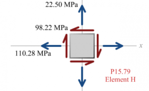
Summary of stresses at H:
\begin{aligned}\sigma_{x} &=99.030 MPa +11.25 MPa =110.280 MPa ( T ) \\\sigma_{z} &=22.50 MPa ( T ) \\\tau_{x z} &=6.264 MPa +91.956 MPa =98.220 MPa\end{aligned}Principal stress calculations for point H:
\begin{aligned}\sigma_{p 1, p 2} &=\frac{(110.280 MPa )+(22.50 MPa )}{2} \pm \sqrt{\left(\frac{(110.280 MPa )-(22.50 MPa )}{2}\right)^{2}+(-98.220 MPa )^{2}} \\&=66.390 MPa \pm 107.580 MPa\end{aligned}therefore, \sigma_{p 1}=173.970 MPa and \sigma_{p 2}=-41.190 MPa
Consider point K.
Force F _{y} creates a transverse shear stress in the xy plane at K. The magnitude of this shear stress is:
Force F _{z} does not cause either a normal stress or a shear stress at K.
Moment M _{x}, which is a torque, creates a torsion shear stress in the xy plane at K. The magnitude of this shear stress is:
\tau_{x y}=\frac{M_{x} c}{J}=\frac{\left(17.0384 \times 10^{6} N – mm \right)(140 mm / 2)}{12.970 \times 10^{6} mm ^{4}}=91.956 MPaMoment M _{y} creates bending stress at K. The magnitude of this stress is:
\sigma_{x}=\frac{M_{y} z}{I_{y}}=\frac{\left(6.4241 \times 10^{6} N – mm \right)(140 mm / 2)}{6.485 \times 10^{6} mm ^{4}}=69.341 MPaMoment M _{z} does not create bending stress at K because K is located on the neutral axis for bending about the z axis.

Summary of stresses at K:
\begin{aligned}\sigma_{x} &=-69.341 MPa +11.25 MPa =58.091 MPa ( C ) \\\sigma_{y} &=22.50 MPa ( T ) \\\tau_{x y} &=-8.946 MPa -91.956 MPa =-100.902 MPa\end{aligned}Principal stress calculations for point K:
\begin{aligned}\sigma_{p 1, p 2} &=\frac{(-58.091 MPa )+(22.50 MPa )}{2} \pm \sqrt{\left(\frac{(-58.091 MPa )-(22.50 MPa )}{2}\right)^{2}+(-100.902 MPa )^{2}} \\&=-17.796 MPa \pm 108.651 MPa\end{aligned}therefore, \sigma_{p 1}=90.855 MPa and \sigma_{p 2}=-126.446 MPa
(a) Maximum-Shear-Stress Theory
Element H:
The factor of safety associated with this state of stress is:
FS _{H}=\frac{240 MPa }{215.160 MPa }=1.115Element K:
\left|\sigma_{p 1}-\sigma_{p 2}\right|=|90.855 MPa -(-126.446 MPa )|=217.301 MPaThe factor of safety associated with this state of stress is:
FS _{K}=\frac{240 MPa }{217.301 MPa }=1.104
(b) Mises equivalent stresses at points H and K:
Element H:
Element K:
\begin{aligned}\sigma_{M, K} &=\left[\sigma_{p 1}^{2}-\sigma_{p 1} \sigma_{p 2}+\sigma_{p 2}^{2}\right]^{1 / 2} \\&=\left[(90.855 MPa )^{2}-(90.855 MPa )(-126.446 MPa )+(-126.446 MPa )^{2}\right]^{1 / 2} \\&=189.028 MPa =189.0 MPa\end{aligned}
(c) Maximum-Distortion-Energy Theory:
Element H:
Element K:
FS _{K}=\frac{240 MPa }{189.028 MPa }=1.270