Cross-sectional area of pipe =\frac{\pi}{4}\left(25 \times 10^{-3}\right)^{2}=0.491 \times 10^{-3} m ^{2}
Fluid velocity, u =\frac{3500}{3600} \times \frac{1}{0.491 \times 10^{-3}} \times \frac{1}{998}=1.98 m / s
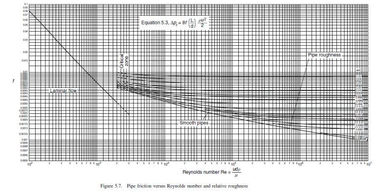
Reynolds number, R e=\left(998 \times 1.98 \times 25 \times 10^{-3}\right) / 0.99 \times 10^{-3} =49,900=5 \times 10^{4} (5.4)
Absolute roughness commercial steel pipe, Table 5.2 = 0.046 mm
Relative roughness =0.046 /\left(25 \times 10^{-3}\right)=0.0018, \text { round to } 0.002
From friction factor chart, Figure 5.7, f = 0.0032
Miscellaneous losses
| Table 5.2. Pipe roughness |
| Material |
Absolute roughness, mm |
| Drawn tubing |
0.0015 |
| Commercial steel pipe |
0.046 |
| Cast iron pipe |
0.26 |
| Concrete pipe |
0.3 to 3.0 |
| fitting/valve |
number of velocity heads, K |
equivalent pipe diameters |
| entry |
0.5 |
25 |
| elbows |
(0.8 \times 4) |
(40 \times 4) |
| globe valve, open |
6.0 |
300 |
| gate valve, 1/2 open |
4.0 |
200 |
| exit |
1.0 |
50 |
| Total |
14.7 |
735 |
Method 1, velocity heads
A velocity head =u^{2} / 2 g=1.98^{2} /(2 \times 9.8)=0.20 m \text { of liquid. }
Head loss =0.20 \times 14.7=2.94 m
as pressure =2.94 \times 998 \times 9.8=28,754 N / m ^{2}
Friction loss in pipe, \Delta P_{f}=8 \times 0.0032 \frac{(120)}{\left(25 \times 10^{-3}\right)} 998 \times \frac{1.98^{2}}{2} =240,388 N / m ^{2} (5.3)
Total pressure =28,754+240,388=269,142 N / m ^{2}=270 kN / m ^{2}
Method 2, equivalent pipe diameters
Extra length of pipe to allow for miscellaneous losses =735 \times 25 \times 10^{-3}=18.4 m
So, total length for \Delta P calculation = 120 + 18.4 = 138.4 m
\begin{aligned}\Delta P_{f} &=8 \times 0.0032 \frac{(138.4)}{\left(25 \times 10^{-3}\right)} 998 \times \frac{1.98^{2}}{2}=277,247 N / m ^{2} \\&=277 kN / m ^{2}\end{aligned} (5.3)
Note: the two methods will not give exactly the same result. The method using velocity heads is the more fundamentally correct approach, but the use of equivalent diameters is easier to apply and sufficiently accurate for use in design calculations.
