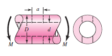
A rotating shaft is made of 42- × 4-mm AISI 1018 cold-drawn steel tubing and has a 6-mm-diameter hole drilled transversely through it. Estimate the factor of safety guarding against fatigue and static failures using the Gerber and Langer failure criteria for the following loading conditions:
(a) The shaft is subjected to a completely reversed torque of 120 N · m in phase with a completely reversed bending moment of 150 N · m.
(b) The shaft is subjected to a pulsating torque fluctuating from 20 to 160 N · m and a steady bending moment of 150 N · m.
Here we follow the procedure of estimating the strengths and then the stresses, followed by relating the two.
From Table A–20 we find the minimum strengths to be S_{ut} = 440 MPa and S_{y} = 370 MPa. The endurance limit of the rotating-beam specimen is 0.5(440) = 220 MPa.
The surface factor, obtained from Eq. (6–19) and Table 6–2, p. 279 is
Table A–20 Deterministic ASTM Minimum Tensile and Yield Strengths for Some Hot-Rolled (HR) and Cold-Drawn (CD) Steels [The strengths listed are estimated ASTM minimum values in the size range 18 to 32 mm ( \frac {3}{4} to 1\frac {1}{4} in). These strengths are suitable for use with the design factor defined in Sec. 1–10, provided the materials conform to ASTM A6 or A568 requirements or are required in the purchase specifications. Remember that a numbering system is not a specification.] Source: 1986 SAE Handbook, p. 2.15.
| 8
Brinell Hardness |
7
Reduction in Area, % |
6
Elongation in 2 in, % |
5
Yield Strength, MPa (kpsi) |
4
Tensile Strength, MPa (kpsi) |
3
Proces-sing |
2
SAE and/or AISI No. |
1
UNS No. |
| 86 | 55 | 30 | 170 (24) | 300 (43) | HR | 1006 | G10060 |
| 95 | 45 | 20 | 280 (41) | 330 (48) | CD | ||
| 95 | 50 | 28 | 180 (26) | 320 (47) | HR | 1010 | G10100 |
| 105 | 40 | 20 | 300 (44) | 370 (53) | CD | ||
| 101 | 50 | 28 | 190 (27.5) | 340 (50) | HR | 1015 | G10150 |
| 111 | 40 | 18 | 320 (47) | 390 (56) | CD | ||
| 116 | 50 | 25 | 220 (32) | 400 (58) | HR | 1018 | G10180 |
| 126 | 40 | 15 | 370 (54) | 440 (64) | CD | ||
| 111 | 50 | 25 | 210 (30) | 380 (55) | HR | 1020 | G10200 |
| 131 | 40 | 15 | 390 (57) | 470 (68) | CD | ||
| 137 | 42 | 20 | 260 (37.5) | 470 (68) | HR | 1030 | G10300 |
| 149 | 35 | 12 | 440 (64) | 520 (76) | CD | ||
| 143 | 40 | 18 | 270 (39.5) | 500 (72) | HR | 1035 | G10350 |
| 163 | 35 | 12 | 460 (67) | 550 (80) | CD | ||
| 149 | 40 | 18 | 290 (42) | 520 (76) | HR | 1040 | G10400 |
| 170 | 35 | 12 | 490 (71) | 590 (85) | CD | ||
| 163 | 40 | 16 | 310 (45) | 570 (82) | HR | 1045 | G10450 |
| 179 | 35 | 12 | 530 (77) | 630 (91) | CD | ||
| 179 | 35 | 15 | 340 (49.5) | 620 (90) | HR | 1050 | G10500 |
| 197 | 30 | 10 | 580 (84) | 690 (100) | CD | ||
| 201 | 30 | 12 | 370 (54) | 680 (98) | HR | 1060 | G10600 |
| 229 | 25 | 10 | 420 (61.5) | 770 (112) | HR | 1080 | G10800 |
| 248 | 25 | 10 | 460 (66) | 830 (120) | HR | 1095 | G10950 |
Table 6–2 Parameters for Marin Surface Modification Factor, Eq.(6–19)
| Exponent b | Factor a | Surface Finish | |
| S_{ut} ,MPa | S_{ut}, kpsi | ||
| −0.085 | 1.58 | 1.34 | Ground |
| −0.265 | 4.51 | 2.70 | Machined or cold-drawn |
| −0.718 | 57.7 | 14.4 | Hot-rolled |
| −0.995 | 272. | 39.9 | As-forged |
k_{a} = a S^{b}_{ut} (6–19)
k_{a} = 4.51S^{−0.265}_{ut} = 4.51(440)^{−0.265} = 0.899
From Eq. (6–20) the size factor is
k_{b}=\begin{cases} (d/0.3)^{−0.107} = 0.879d^{−0.107} & 0.11 ≤ d ≤ 2 in \\ 0.91d^{−0.157} & 2 < d ≤ 10 in \\ (d/7.62)^{−0.107} = 1.24d^{−0.107} & 2.79 ≤ d ≤ 51 mm \\ 1.51d^{−0.107} & 51 < d ≤ 254 mm \end{cases} (6-20)
k_{b} =\left( \frac {d}{7.62}\right)^{−0.107}=\left( \frac {42}{7.62}\right)^{−0.107}= 0.833
The remaining Marin factors are all unity, so the modified endurance strength S_{e} is
S_{e} = 0.899(0.833)220 = 165 MPa
(a) Theoretical stress-concentration factors are found from Table A–16. Using a/D = 6/42 = 0.143 and d/D = 34/42 = 0.810, and using linear interpolation, we obtain A = 0.798 and K_{t} = 2.366 for bending; and A = 0.89 and K_{ts} = 1.75 for torsion.
Thus, for bending,
Table A–16 Approximate Stress-Concentration Factor K_{t} for Bending of a Round Bar or Tube with a Transverse Round Hole Source: R. E. Peterson, Stress Concentration Factors, Wiley, New York, 1974, pp. 146,235.
The nominal bending stress is σ_{0} = M/Z_{net} where Z_{net} is a reduced value of the section modulus and is defined by
Z_{net} =\frac {π A}{32D}(D^{4} − d^{4})
Values of A are listed in the table. Use d = 0 for a solid bar
| d/D | ||||||
| 0 | 0.6 | 0.9 | ||||
| K_{t} | A | K_{t} | A | K_{t} | A | a/D |
| 2.42 | 0.88 | 2.55 | 0.91 | 2.63 | 0.92 | 0.050 |
| 2.35 | 0.86 | 2.43 | 0.88 | 2.55 | 0.89 | 0.075 |
| 2.27 | 0.83 | 2.36 | 0.85 | 2.49 | 0.86 | 0.10 |
| 2.20 | 0.80 | 2.32 | 0.82 | 2.41 | 0.86 | 0.125 |
| 2.15 | 0.76 | 2.29 | 0.79 | 2.39 | 0.79 | 0.15 |
| 2.10 | 0.72 | 2.26 | 0.75 | 2.38 | 0.76 | 0.175 |
| 2.07 | 0.68 | 2.23 | 0.72 | 2.39 | 0.73 | 0.20 |
| 2.04 | 0.65 | 2.21 | 0.68 | 2.40 | 0.69 | 0.225 |
| 2.00 | 0.61 | 2.18 | 0.64 | 2.42 | 0.67 | 0.25 |
| 1.97 | 0.58 | 2.16 | 0.61 | 2.48 | 0.66 | 0.275 |
| 1.94 | 0.54 | 2.14 | 0.58 | 2.52 | 0.64 | 0.30 |
Z_{net} =\frac {π A}{32D}(D^{4} − d^{4}) =\frac {π(0.798)}{32(42)}[(42)^{4} − (34)^{4}] = 3.31 (10^{}3) mm^{3}
and for torsion
J_{net }=\frac {π A}{32}(D^{4} − d^{4}) =\frac {π(0.89)}{32}[(42)^{4} − (34)^{4}] = 155 (10^{3}) mm^{4}
Next, using Figs. 6–20 and 6–21, pp. 287–288, with a notch radius of 3 mm we find the notch sensitivities to be 0.78 for bending and 0.96 for torsion. The two corresponding fatigue stress-concentration factors are obtained from Eq. (6–32) as
K_{f} = 1 + q(K_{t} − 1) = 1 + 0.78(2.366 − 1) = 2.07
K_{f s} = 1 + 0.96(1.75 − 1) = 1.72
The alternating bending stress is now found to be
σ_{xa} = K_{f} \frac {M}{Z_{net}} = 2.07 \frac {150}{3.31(10^{−6})} = 93.8(10^{6})Pa = 93.8 MPa
and the alternating torsional stress is
τ_{xya} = K_{f s} \frac {TD}{2J_{net}} = 1.72 \frac{120(42)(10^{−3})}{2(155)(10^{−9}) }= 28.0(10^{6})Pa = 28.0 MPa
The midrange von Mises component σ′_{m} is zero. The alternating component σ′_{a} is given by
σ′_{a }=\left(σ^{2}_{xa} + 3τ^{2}_{xya}\right)^{1/2}= [93.8^{2} + 3(28^{2})]^{1/2} = 105.6 MPa
Since S_{e} = S_{a} , the fatigue factor of safety n_{f} is
n_{f} =\frac {S_{a}}{σ′_{a}} =\frac {165}{105.6} = 1.56
The first-cycle yield factor of safety is
n_{y} =\frac {S_{y}}{σ′_{a}} =\frac {370}{105.6} = 3.50
There is no localized yielding; the threat is from fatigue. See Fig. 6–32.
(b) This part asks us to find the factors of safety when the alternating component is due to pulsating torsion, and a steady component is due to both torsion and bending. We have T_{a} = (160 − 20)/2 = 70 N · m and T_{m} = (160 + 20)/2 = 90 N · m. The corresponding amplitude and steady-stress components are
τ_{xya} = K_{f s} \frac{T_{a}D}{2J_{net}} = 1.72 \frac{70(42)(10^{−3})}{2(155)(10^{−9}) }= 16.3(10^{6}) Pa = 16.3 MPa
τ_{xym} = K_{f s} \frac{T_{m}D}{2J_{net}} = 1.72 \frac{90(42)(10^{−3})}{2(155)(10^{−9}) }= 21.0(10^{6}) Pa = 21.0 MPa
The steady bending stress component σ_{xm} is
σ_{xm} = K_{f} \frac {M_{m}}{Z_{net}} = 2.07 \frac {150}{3.31(10^{−6})} = 93.8(10^{6}) Pa = 93.8 MPa
The von Mises components σ′_{a} and σ′_{m} are
σ′_{a} = [3(16.3)^{2}]^{1/2} = 28.2 MPa
σ′_{m} = [93.8^{2} + 3(21)^{2}]^{1/2} = 100.6 MPa
From Table 6–7, p. 299, the fatigue factor of safety is
Table 6–7 Amplitude and Steady Coordinates of Strength and Important Intersections in First Quadrant for Gerber and Langer Failure Criteria
| Intersection Coordinates | Intersecting Equations |
| S_{a} =\frac {r^{2}S^{2}_{ut}}{2S_{e}} \left [-1+\sqrt {1+\left (\frac {2S_{e}}{rS_{ut}}\right)^{2}}\right]
S_{m} =\frac {S_{a}}{r} |
\frac {S_{a}}{S_{e}} +\left (\frac {S_{m}}{S_{ut}}\right)^{2}= 1
Load line r =\frac {S_{a}}{S_{m}} |
| S_{a} =\frac {r S_{y}}{1 + r}
S_{m} =\frac {S_{y}}{1 + r} |
\frac {S_{a}}{S_{y}} +\frac {S_{m}}{S_{y}} = 1
Load line r =\frac {S_{a}}{S_{m}} |
| S_{m} =\frac {S^{2}_{ut}}{2S_{e}} \left [1 − \sqrt{1 + \left(\frac {2S_{e}}{S_{ut}}\right)^{2} \left(1 − \frac {S_{y}}{S_{e}}\right) }\right]
S_{a} = S_{y} − S_{m},r_{crit} = S_{a}/S_{m} |
\frac {S_{a}}{S_{e}} +\left (\frac {S_{m}}{S_{ut}}\right)^{2}= 1
\frac {S_{a}}{S_{y}} +\frac {S_{m}}{S_{y}} = 1 |
| Fatigue factor of safety
n_{f} =\frac {1}{2} \left(\frac {S_{ut}}{σ_{m}}\right)^{2} \frac {σ_{a}}{S_{e}} \left [-1+\sqrt {1+\left (\frac {2σ_{m} S_{e}}{ S_{ut}σ_{a}}\right)^{2}}\right] σ_{m}>0 |
|
n_{f} =\frac {1}{2} \left(\frac {440}{100.6} \right)^{ 2} \frac { 28.2}{165} \left\{-1+\sqrt{1+ \left[\frac {2(100.6)165}{440(28.2)}\right]^{2}}\right\}= 3.03
From the same table, with r = σ′_{a} /σ′_{m} = 28.2/100.6 = 0.280, the strengths can be shown to be S_{a} = 85.5 MPa and S_{m} = 305 MPa. See the plot in Fig. 6–32.
The first-cycle yield factor of safety n_{y} is
n_{y} =\frac {S_{y}}{σ′_{a} + σ′_{m}} =\frac {370}{28.2 + 100.6} = 2.87
There is no notch yielding. The likelihood of failure may first come from first-cycle yielding at the notch. See the plot in Fig. 6–32.


