Question : Analysis of Heat Conduction in a Chip A chip is dissipating ...

Analysis of Heat Conduction in a Chip

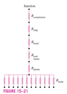
A chip is dissipating 0.6 W of power in a DIP with 12 pin leads. The materials and the dimensions of various sections of this electronic device are as given in the table below. If the temperature of the leads is 40^{\circ}C, estimate the temperature at the junction of the chip.


Section and Material Thermal Conductivity, W/m · °C  Thickness, mm Heat Transfer
Junction constriction  — diameter 0.4 mm
Silicon chip 120^{†}  0.4 3 mm × 3 mm
Eutectic bond 296 0.03 3 mm × 3 mm
Copper lead frame 386 0.25 3 mm × 3 mm
Plastic separator 1 0.2 12 × 1 mm × 0.25 mm
Copper leads 386 5 12 × 1 mm × 0.25 mm


^{†} The thermal conductivity of silicon varies greatly with temperature from 153.5  W/m \cdot  ^{\circ}C at 27^{\circ}C to 113.7  W/m \cdot  ^{\circ}C at 100^{\circ}C , and the value 120  W/m \cdot  ^{\circ}C reflects the anticipation that the temperature of the silicon chip will be close to 100^{\circ}C .

The Blue Check Mark means that this solution has been answered and checked by an expert. This guarantees that the final answer is accurate.
Learn more on how we answer questions.

SOLUTION  The dimensions and power dissipation of a chip are given. The junction temperature of the chip is to be determined.

Assumptions  1 Steady operating conditions exist. 2 Heat transfer through various components is one-dimensional. 3 Heat transfer through the air gap and the lid on top of the chip is negligible because of the very large thermal resistance involved along this path.

Analysis  The geometry of the device is as shown in Figure 15–20. We take the primary heat flow path to be the chip, the eutectic bond, the lead frame, the plastic insulator, and the 12 leads. When the constriction resistance between the junction and the chip is considered, the thermal resistance network for this problem becomes as shown in Figure 15–21. The various thermal resistances on the path of primary heat flow are determined as follows.

R_{constriction} = \frac{1}{2 \sqrt{\pi } dk} = \frac{1}{\sqrt{\pi } \left ( 0.4 \times 10^{-3}  m \right )\left ( 120  W/m \cdot  ^{\circ}C \right )} = 5.88^{\circ}C/W


R_{chip} = \left ( \frac{L}{kA} \right )_{chip} = \frac{0.4 \times 10^{-3}  m}{\left ( 120  W/m \cdot  ^{\circ}C \right )\left ( 9 \times 10^{-6}  m^{2} \right )} = 0.37^{\circ}C/W


R_{bond} = \left ( \frac{L}{KA} \right )_{bond} = \frac{0.03 \times 10^{-3}  m}{\left ( 296  W/m \cdot  ^{\circ}C \right )\left ( 9 \times 10^{-6}  m^{2} \right )} = 0.01^{\circ}C/W


R_{lead  frame} = \left ( \frac{L}{kA} \right )_{lead  frame} = \frac{0.25 \times 10^{-3}  m}{\left ( 386  W/m \cdot  ^{\circ}C \right )\left ( 9 \times 10^{-6}  m^{2} \right )}


                                                                                           = 0.07^{\circ}C/W


R_{plastic} = \left ( \frac{L}{kA} \right )_{plastic} = \frac{0.2 \times 10^{-3}  m}{\left ( 1  W/m \cdot  ^{\circ}C \right )\left (12 \times 0.25 \times 10^{-6}  m^{2} \right )} = 66.67^{\circ}C/W


R_{leads} = \left ( \frac{L}{kA} \right )_{leads} = \frac{5 \times 10^{-3}  m}{\left ( 386  W/m \cdot  ^{\circ}C \right )\left (12 \times 0.25 \times 10^{-6}  m^{2} \right )} = 4.32^{\circ}C/W


Note that for heat transfer purposes, all 12 leads can be considered as a single lead whose cross-sectional area is 12 times as large. The alternative is to find the resistance of a single lead and to calculate the equivalent resistance for 12 such resistances connected in parallel. Both approaches give the same result. All the resistances determined here are in series. Thus the total thermal resistance between the junction and the leads is determined by simply adding them up:

R_{total} = R_{junction-lead} = R_{constriction} + R_{chip} + R_{bond} + 


                                                      R_{lead frame} + R_{plastic} + R_{leads}


= \left ( 5.88 + 0.37 + 0.01 + 0.07 + 66.67 + 4.32 \right )^{\circ} C/W


= 77.32^{\circ} C/W


Heat transfer through the chip can be expressed as

                        \dot{Q} = \left ( \frac{\Delta T}{R} \right )_{junction-leads} = \frac{T_{junction}  –  T_{leads}}{R_{junction-leads}}


Solving for T_{junction} and substituting the given values, the junction temperature is determined to be

               T_{junction} = T_{leads} + \dot{Q} R_{junction-leads}


                         = 40^{\circ}C + \left ( 0.6  W \right )\left ( 77.32^{\circ}C/ W \right ) = 86.4^{\circ}C


Note that the plastic layer between the lead frame and the leads accounts for 66.67/77.32 = 86 percent of the total thermal resistance and thus the 86 percent of the temperature drop \left ( 0.6 \times 66.67 = 40^{\circ}C \right ) between the junction and the leads. In other words, the temperature of the junction would be just 86.5  –  40 = 46.5^{\circ}C if the thermal resistance of the plastic was eliminated.


Discussion  The simplified analysis given here points out that any attempt to reduce the thermal resistance in the chip carrier and thus improve the heat flow path should start with the plastic layer. We also notice from the magnitudes of individual resistances that some sections, such as the eutectic bond and the lead frame, have negligible thermal resistances, and any attempt to improve them further will have practically no effect on the junction temperature of the chip.

3
4