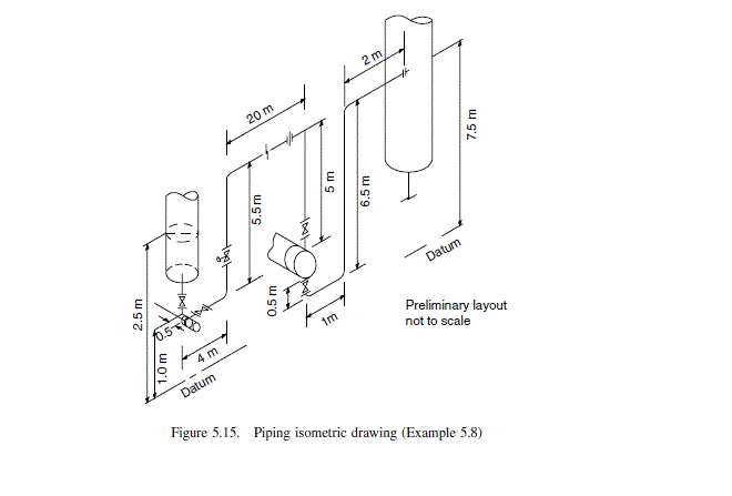
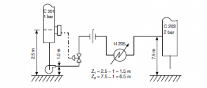
Calculate the line size and specify the pump required for the line shown in Figure 5.15; material ortho dichlorobenzene (ODCB), flow-rate 10,000 kg/h, temperature 20^{\circ} C, pipe material carbon steel.
Question 5.8: Calculate the line size and specify the pump required for th...

The Blue Check Mark means that this solution has been answered and checked by an expert. This guarantees that the final answer is accurate.
Learn more on how we answer questions.
Learn more on how we answer questions.
ODCB density at 20ŽC D 1306 kg / m ^{3}.
Viscosity: 0.9 mNs / m ^{2} (0.9 cp).
Estimation of pipe diameter required
typical velocity for liquid 2 m/s
mass flow =\frac{10,000}{3600}=2.78 kg / s
volumetric flow =\frac{2.78}{1306}=2.13 \times 10^{-3} m ^{3} / s
area of pipe =\frac{\text { volumetric flow }}{\text { velocity }}=\frac{2.13 \times 10^{-3}}{2}=1.06 \times 10^{-3} m ^{2}
diameter of pipe =\sqrt{\left(1.06 \times 10^{-3} \times \frac{4}{\pi}\right)}=0.037 m = 37 mm
Or, use economic pipe diameter formula:
d, optimum =293 \times 2.78^{0.53} \times 1306^{-0.37} = 35.4 mm (5.14)
Take diameter as 40 mm
cross-sectional area =\frac{\pi}{4}\left(40 \times 10^{-3}\right)=1.26 \times 10^{-3} m ^{2}
Pressure drop calculation
\text { fluid velocity }=\frac{2.13 \times 10^{-3}}{1.26 \times 10^{-3}}=1.70 m / s
Friction loss per unit length, \Delta f_{1}:
R e=\frac{1306 \times 1.70 \times 40 \times 10^{-3}}{0.9 \times 10^{-3}}=9.9 \times 10^{4} (5.5)
Absolute roughness commercial steel pipe, table 5.2 = 0.46 mm
| Table 5.2. Pipe roughness | |
| Material | Absolute roughness, mm |
| Drawn tubing | 0.0015 |
| Commercial steel pipe | 0.046 |
| Cast iron pipe | 0.26 |
| Concrete pipe | 0.3 to 3.0 |
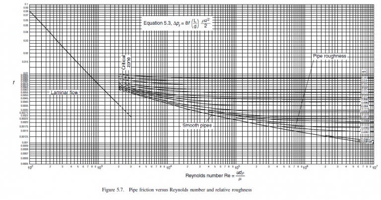
Relative roughness, e/d D 0.046/40 = 0.001
Friction factor from Figure 5.7, f = 0.0027
\begin{aligned}\Delta f_{1} &=8 \times 0.0027 \times \frac{(1)}{\left(40 \times 10^{-3}\right)} \times 1306 \times \frac{1.7^{2}}{2}=1019 N / m ^{2} \\&=1.02 kPa\end{aligned} (5.3)
Design for a maximum flow-rate of 20 per cent above the average flow.
\text { Friction loss }=1.02 \times 1.2^{2}=1.5 kPa / m
Miscellaneous losses
Take as equivalent pipe diameters. All bends will be taken as 90Ž standard radius elbow.
Line to pump suction:
| length = 1.5 m |
| \text { bend, } 1 \times 30 \times 40 \times 10^{-3}1.2m |
| \text { valve, } 1 \times 18 \times 40 \times 10^{-3}0.7m |
| 3.4 m |
\text { entry loss }=\frac{\rho u^{2}}{2}(\text { see Section 5.4.2) }
\text { at maximum design velocity }=\frac{1306(1.7 \times 1.2)^{2}}{2 \times 10^{3}}=2.7 kPa
Control valve pressure drop, allow normal 140 kPa
\left(\times 1.2^{2}\right) maximum 200 kPa
Heat exchanger, allow normal 70 kPa
\left(\times 1.2^{2}\right) maximum 100 kPa
Orifice, allow normal 15 kPa
\left(\times 1.2^{2}\right) maximum 22 kPa
Line from pump discharge:
| \text { length }=4+5.5+20+5+0.5+1+6.5+2=44.5 m |
| \text { bends, } 6 \times 30 \times 40 \times 10^{-3}=7.2 \quad=7.2 m |
| \text { valves, } 3 \times 18 \times 40 \times 10^{-3}=2.2 \quad=2.2 m |
| 54.0 m |
The line pressure-drop calculation is set out on the calculation sheet shown in Table 5.4.
Pump selection:
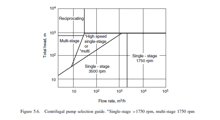
\text { flow-rate }=2.13 \times 10^{-3} \times 3600=7.7 m ^{3} / h
differential head, maximum, 44 m
select single-stage centrifugal (Figure 5.6)
| Table 5.4. Line calculation form (Example 5.4) | |||||||||
| Pump and line calculation sheet | |||||||||
| Job no. | Sheet no. | By RKS, 7/7/79 | Checked | ||||||
| 4415A | 1 | ||||||||
| Fluid | ODCB | DISCHARGE CALCULATION | |||||||
| Temperature °C | 20 | Line size mm | 40 | ||||||
| Density kg / m ^{3} | 1306 | Flow | Norm. | Max. | Units | ||||
| Viscosity mNs / m ^{2} | 0.9 | u _{2} | Velocity | 1.7 | 2.0 | m/s | |||
| Normal flow kg/s | 2.78 | \Delta f _{2} | Friction loss | 1.0 | 1.5 | kPa/m | |||
| Design max. flow kg/s | 3.34 | L _{2} | Line length | 54 | _ | m | |||
| \Delta f _{2} L _{2} | Line loss | 54 | kPa | ||||||
| SUCTION CALCULATION | Orifice | 15 | 22 | kPa | |||||
| Line size mm | 40 | 30 \% | Control valve | 140 | 200 | kPa | |||
| Flow | Norm. | Max. | Units | Equipment | |||||
| u _{1} | Velocity | 1.7 | 2.0 | m/s | (a) Heat ex. | 70 | 100 | kPa | |
| \Delta f _{1} | Friction loss | 1.0 | 1.5 | kPa/m | (b) | _ | _ | kPa | |
| L _{1} | Line length | 3.4 | _ | m | (c) | _ | _ | kPa | |
| \Delta f _{1} L _{1} | Line loss | 3.4 | 5.1 | kPa | (6) Dynamic loss | 279 | 403 | kPa | |
| \rho u _{1}^{2} / 2 | Entrance | 1.9 | 2.7 | kPa | Z _{2} | Static head | 6.5 | _ | m |
| (40 kPa) | Strainer | _ | _ | kPa | \rho g Z _{2} | 85 | 85 | kPa | |
| (1) Sub-total | 5.3 | 7.8 | kPa | Equip. press (max) | 200 | 200 | kPa | ||
| Z _{1} | Static head | 1.5 | 1.5 | m | Contingency | None | None | kPa | |
| \rho gZ _{1} | 19.6 | 19.6 | kPa | (7) Sub-total | 285 | 285 | kPa | ||
| Equip. press | 100 | 100 | kPa | (7) + (6) | Discharge press. | 564 | 685 | kPa | |
| (2) Sub-total | 119.6 | 119.6 | kPa | (3) | Suction press. | 114.3 | 111.8 | kPa | |
| (2)-(1) | (3) Suction press | 114.3 | 111.8 | kPa | (8) Diff. press. | 450 | 576 | kPa | |
| (4) VAP. PRESS. | 0.1 | 0.1 | kPa | (8) / \rho g | 34 | 44 | m | ||
| (3)-(4) | (5) NPSH | 114.2 | 111.7 | kPa | Valve/(6) | Control valve % Dyn. Loss | 50% | ||
| (5) / \rho g | 8.7 | 8.6 | m | ||||||
 |
|||||||||
| Table 5.5. Pump Specification Sheet (Example 5.8) | |
| Pump Specification | |
| Type: | Centrifugal |
| No. stages: | 1 |
| Single/Double suction: | Single |
| Vertical/Horizontal mounting: | Horizontal |
| Impeller type: | Closed |
| Casing design press.: | 600 kPa |
| design temp.: | 20^{\circ} C |
| Driver: | Electric, 440 V, 50 c/s 3-phase. |
| Seal type: | Mechanical, external flush |
| Max. flow: | 7.7 m ^{3} / h |
| Diff. press.: | 600 kPa (47 m, water) |


Related Answered Questions
Cross-sectional area of pipe =\frac{\pi}{4}...
Cross-sectional area of pipe =\frac{\pi}{4}...
Static head
Difference in elevation, \Delta...
Friction losses
Miscellaneous losses =1000 ...
d, optimum =293 \times(10)^{0.53} 1000^{-0....
Molecular weight HCl = 36.5.
Density at operating ...