Known An air compressor operates at steady state with known inlet and exit states and a known heat transfer rate.
Find Calculate the power required by the compressor.
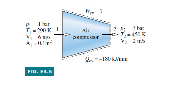
Schematic and Given Data:
Engineering Model
1. The control volume shown on the accompanying figure is at steady state.
2. The change in potential energy from inlet to exit can be neglected.
1 3. The ideal gas model applies for the air.
Analysis To calculate the power input to the compressor, begin with the one-inlet, one-exit form of the energy rate balance for a control volume at steady state, Eq. 4.20a. That is,
0=\dot{Q}_{ cv }-\dot{W}_{ cv }+\dot{m}\left[\left(h_{1}-h_{2}\right)+\frac{\left( V _{1}^{2}- V _{2}^{2}\right)}{2}+g\left(z_{1}-z_{2}\right)\right] (4.20a)
0=\dot{Q}_{ cv }-\dot{W}_{ cv }+\dot{m}\left[\left(h_{1}-h_{2}\right)+\frac{\left( V _{1}^{2}- V _{2}^{2}\right)}{2}+g\left(z_{1}-z_{2}\right)\right]
Solving
\dot{W}_{ cv }=\dot{Q}_{ cv }+\dot{m}\left[\left(h_{1}-h_{2}\right)+\left(\frac{ V _{1}^{2}- V _{2}^{2}}{2}\right)\right]
The change in potential energy from inlet to exit drops out by assumption 2.
The mass flow rate \dot{m} can be evaluated with given data at the inlet and the ideal gas equation of state.
\dot{m}=\frac{ A _{1} V _{1}}{v_{1}}=\frac{ A _{1} V _{1} p_{1}}{(\bar{R} / M) T_{1}}=\frac{\left(0.1 m ^{2}\right)(6 m / s )\left(10^{5} N / m ^{2}\right)}{\left(\frac{8314}{28.97} \frac{ N \cdot m }{ kg \cdot K }\right)(290 K )}=0.72 kg / s
The specific enthalpies h_{1} \text { and } h_{2} can be found from Table A-22. At 290 K, h_{1}=290.16 kJ / kg . \text { At } 450 K , h_{2}=451.8 kJ / kg. Substituting values into the expression for \dot{W}_{\text {cv }} , and applying appropriate unit conversion factors, we get
\dot{W}_{ cv }=\left(-180 \frac{ kJ }{ min }\right)\left|\frac{1 min }{60 s }\right|+0.72 \frac{ kg }{ s }\left[(290.16-451.8) \frac{ kJ }{ kg }\right.
\left.+\left(\frac{(6)^{2}-(2)^{2}}{2}\right)\left(\frac{ m ^{2}}{ s ^{2}}\right)\left|\frac{1 N }{1 kg \cdot m / s ^{2}}\right| \left| \frac{1 kJ }{10^{3} N \cdot m }\right|\right]
=-3 \frac{ kJ }{ s }+0.72 \frac{ kg }{ s }(-161.64+0.02) \frac{ kJ }{ kg }
2 =-119.4 \frac{ kJ }{ s }\left|\frac{1 kW }{1 kJ / s }\right|=-119.4 kW
1 The applicability of the ideal gas model can be checked by reference to the generalized compressibility chart.
2 In this example \dot{Q}_{ cv } \text { and } \dot{W}_{ cv } have negative values, indicating that the direction of the heat transfer is from the compressor and work is done on the air passing through the compressor. The magnitude of the power input to the compressor is 119.4 kW. The change in kinetic energy does not contribute significantly.
Skills Developed
Ability to…
• apply the steady-state energy rate balance to a control volume.
• apply the mass flow rate expression, Eq. 4.4b.
\dot{m}=\frac{ AV }{v} (one-dimensional flow) (4.4b)
• develop an engineering model.
• retrieve property data of air modeled as an ideal gas.
Quick Quiz
If the change in kinetic energy from inlet to exit were neglected, evaluate the compressor power, in kW, keeping all other data unchanged. Comment. Ans. −119.4 kW.