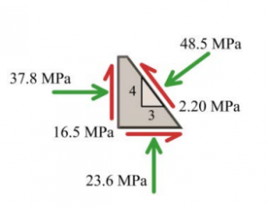
Consider a point in a structural member that is subjected to plane stress. Normal and shear stresses acting on horizontal and vertical planes at the point are shown.
(a) Draw Mohr’s circle for this state of stress.
(b) Determine the principal stresses and the maximum in-plane shear stress acting at the point. Show these stresses on an appropriate sketch (e.g., see Figure 12.15 or Figure 12.16).
(c) Determine the normal and shear stresses on the indicated plane and show these stresses on a sketch.
(d) Determine the absolute maximum shear stress at the point.
Instructors: Problems 12.81-12.84 should be assigned as a set.


(b) The basic Mohr’s circle is shown.
\begin{aligned}&C=\frac{(-37.8 MPa )+(-23.6 MPa )}{2}=-30.7 MPa \\&R=\sqrt{(7.1 MPa )^{2}+(16.5 MPa )^{2}}=17.9627 MPa\end{aligned}\begin{aligned}&\sigma_{p 1}=C+R=-30.7 MPa +17.9627 MPa =-12.74 MPa \\&\sigma_{p 2}=C-R=-30.7 MPa -17.9627 MPa =-48.7 MPa \\&\tau_{\max }=R=17.96 MPa \\&\sigma_{\text {avg }}=C=30.7 MPa ( C )\end{aligned}
The magnitude of the angle 2 \theta_{p} between point x (i.e., the x face of the stress element) and point 2 (i.e., the principal plane subjected to \sigma_{p 2}) is found from:
\tan 2 \theta_{p}=\frac{16.5 MPa }{|(-37.8 MPa )-(-30.7 MPa )|}=\frac{16.5 MPa }{7.1 MPa }=2.3239 \therefore 2 \theta_{p}=66.7176^{\circ} \quad \text { thus, } \theta_{p}=33.4^{\circ}By inspection, the angle \theta_{p} from point x to point 2 is turned counterclockwise. The orientation of the principal stresses and the maximum in-plane shear stress is shown in the sketch below.

(c) To determine the normal and shear stresses on the indicated plane, we must first determine the orientation of the plane relative to the x face of the stress element. Looking at the stress element, we Excerpts from this work may be reproduced by instructors for distribution on a not-for-profit basis for testing or instructional purposes only to students enrolled in courses for which the textbook has been adopted. Any other reproduction or translation of this work beyond that permitted by Sections 107 or 108 of the 1976 United States Copyright Act without the permission of the copyright owner is unlawful. observe that the normal to the indicated plane is oriented 36.87° counterclockwise from the x axis. In Mohr’s circle, all angle measures are doubled; therefore, point n (which represents the state of stress on the n plane) on Mohr’s circle is rotated 2(36.87°) = 73.74° counterclockwise from point x. The angle between point n and point 2 is
\beta=66.7176^{\circ}-73.7398^{\circ}=-7.0222^{\circ}
The σ coordinate of point n is found from:
\begin{aligned}\sigma_{n} &=C-R \cos \beta \\&=-30.7 MPa -(17.9627 MPa ) \cos \left(-7.0222^{\circ}\right) \\&=-48.5280 MPa =48.5 MPa ( C )\end{aligned}The τ coordinate of point n is found from:
\begin{aligned}\tau_{n t} &=R \sin \beta \\&=(17.9627 MPa ) \sin \left(7.0222^{\circ}\right)=2.1960 MPa =2.20 MPa\end{aligned}Since point n is below the σ axis, the shear stress acting on the plane surface tends to rotate the stress element counterclockwise.
(d) Since the point in a structural member is subjected to plane stress
\sigma_{z}=\sigma_{p 3}=0Three Mohr’s circles can be constructed to show stress combinations in the \sigma_{p 1}-\sigma_{p 2} plane, the \sigma_{p 1}-\sigma_{p 3} plane, and the \sigma_{p 2}-\sigma_{p 3} plane. These three circles are shown below.

In this case, the absolute maximum shear stress occurs in the \sigma_{p 2}-\sigma_{p 3} plane; therefore,
\tau_{ abs \max }=\frac{\left|\sigma_{p 2}-\sigma_{p 3}\right|}{2}=\frac{|-48.6627 MPa -0 MPa |}{2}=24.3 MPa