Question 9.26: Consider the forces acting on the intermediate shaft of a ge...

Consider the forces acting on the intermediate shaft of a gearbox illustrated in Example 9.4. The maximum permissible radial deflection at any gear is limited to 1 mm. The modulus of elasticity of the shaft material is 207000 N/mm². Determine the shaft diameter and compare it with the solution of Example 9.4.

Table 9.4 Bending moment and deflection of beams

Consider the forces acting on the intermediate shaft of a gearbox illustrated in Example 9.4. The maximum permissible radial deflection at any gear is limited to 1 mm. The modulus of elasticity of the shaft material is 207000 N/mm^2. Determine the shaft diameter and compare it with the solution of Case 1 Cantilever Beam – End load
(A) Bending moments

\left(M_{b}\right) \text { at } O=-P l.         (1).

\left(M_{b}\right) \text { at } x=-P(l-x) .             (2).

(B) Deflections

\delta \text { at } x=\frac{P x^{2}}{6 E I}(x-3 l)              (3).

\delta_{\max .} \text { at }(x=l)=-\frac{P l^{3}}{3 E I}              (4).

Consider the forces acting on the intermediate shaft of a gearbox illustrated in Example 9.4. The maximum permissible radial deflection at any gear is limited to 1 mm. The modulus of elasticity of the shaft material is 207000 N/mm^2. Determine the shaft diameter and compare it with the solution of Case 2 Cantilever Beam—Uniformly distributed load
(A) Bending moments

\left(M_{b}\right) \text { at } O=-\frac{w l^{2}}{2}            (5).

\left(M_{b}\right) \text { at } x=-\frac{w(l-x)^{2}}{2}             (6).

(B) Deflections

\delta \text { at } x=\frac{w x^{2}}{24 E I}\left(4 l x-x^{2}-6 l^{2}\right)            (7).

\delta_{\max .} \text { at }(x=l)=-\frac{w l^{4}}{8 E I}           (8).

Consider the forces acting on the intermediate shaft of a gearbox illustrated in Example 9.4. The maximum permissible radial deflection at any gear is limited to 1 mm. The modulus of elasticity of the shaft material is 207000 N/mm^2. Determine the shaft diameter and compare it with the solution of Case 3 Cantilever Beam—Moment load
(A) Bending moments

\left(M_{b}\right) \text { at } O=\left(M_{b}\right) \text { at } x=\left(M_{b}\right)_{B}            (9).

(B) Deflections

\delta \text { at } x=\frac{\left(M_{b}\right)_{B} x^{2}}{2 E I}           (10).

\delta_{\max .} \text { at }(x=l)=\frac{\left(M_{b}\right)_{B} l^{2}}{2 E I}          (11).

Consider the forces acting on the intermediate shaft of a gearbox illustrated in Example 9.4. The maximum permissible radial deflection at any gear is limited to 1 mm. The modulus of elasticity of the shaft material is 207000 N/mm^2. Determine the shaft diameter and compare it with the solution of Case 4 Simply supported beam—Centre load
(A) Bending moments

\left(M_{b}\right) \text { at } x=\frac{P x}{2}            (12).

\left(M_{b}\right) \text { at } x=\frac{P(l-x)}{2} \quad(x>1 / 2)            (13).

\left(M_{b}\right) \text { at } B=\frac{P l}{4}          (14).

(B) Deflections

\delta \text { at } x=\frac{P x\left(4 x^{2}-3 l^{2}\right)}{48 E I} \quad(0<x<1 / 2)              (15).

\delta_{\max .} \text { at } B=-\frac{P l^{3}}{48 E I}                   (16).

Consider the forces acting on the intermediate shaft of a gearbox illustrated in Example 9.4. The maximum permissible radial deflection at any gear is limited to 1 mm. The modulus of elasticity of the shaft material is 207000 N/mm^2. Determine the shaft diameter and compare it with the solution of Case 5 Simply supported Beam—Uniformly distributed load
(A) Bending moments

\left(M_{b}\right) \text { at } x=\frac{w x(l-x)}{2}         (17).

\left(M_{b}\right) \text { at } l / 2=\frac{w l^{2}}{8}           (18).

(B) Deflections

\delta \text { at } x=\frac{w x\left(2 l x^{2}-x^{3}-l^{3}\right)}{24 E I}            (19)

\delta_{\max .} \text { at } l / 2=-\frac{5 w l^{4}}{384 E I}                 (20).

Consider the forces acting on the intermediate shaft of a gearbox illustrated in Example 9.4. The maximum permissible radial deflection at any gear is limited to 1 mm. The modulus of elasticity of the shaft material is 207000 N/mm^2. Determine the shaft diameter and compare it with the solution of Case 6 Simply supported beam—Moment load
(A) Bending moments

\left(M_{b}\right) \text { at } x=\frac{\left(M_{b}\right)_{B} x}{l}(0<x<a)                     (21).

\left(M_{b}\right) \text { at } x=\frac{\left(M_{b}\right)_{B}(x-l)}{l}(a<x<l)               (22).

(B) Deflections

\delta \text { at } x=\frac{\left(M_{b}\right)_{B} x\left(x^{2}+3 a^{2}-6 a l+2 l^{2}\right)}{6 E I l} \quad(0<x< a )           (23).

\delta \text { at } x=\frac{\left(M_{b}\right)_{B}\left[x^{3}-3 l x^{2}+x\left(2 l^{2}+3 a^{2}\right)-3 a^{2} l\right]}{6 E I l}           (a < x < l)              (24).

Consider the forces acting on the intermediate shaft of a gearbox illustrated in Example 9.4. The maximum permissible radial deflection at any gear is limited to 1 mm. The modulus of elasticity of the shaft material is 207000 N/mm^2. Determine the shaft diameter and compare it with the solution of Case 7 Simply supported Beam—Intermediate load
(A) Bending moment

\left(M_{b}\right) \text { at } x=\frac{P b x}{l} \quad(0<x<a)             (25).

\left(M_{b}\right) \text { at } x=\frac{P a(l-x)}{l} \quad( a <x<l)           (26).

(B) Deflections

\delta \text { at } x=\frac{P b x\left(x^{2}+b^{2}-l^{2}\right)}{6 E I l} \quad(0<x<a)        (27).

\delta \text { at } x=\frac{P a(l-x)\left(x^{2}+a^{2}-2 l x\right)}{6 E I l}(a<x<l)            (28).

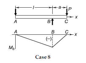
Consider the forces acting on the intermediate shaft of a gearbox illustrated in Example 9.4. The maximum permissible radial deflection at any gear is limited to 1 mm. The modulus of elasticity of the shaft material is 207000 N/mm^2. Determine the shaft diameter and compare it with the solution of Case 8 Simply supported beam—Overhang load
(A) Bending moments

\left(M_{b}\right) \text { at } x=-\frac{P a x}{l} \quad(x<l) .             (29)

\left(M_{b}\right) \text { at } x=P(x-l-a) \quad(x>l)           (30)

(B) Deflections

\delta \text { at } x=\frac{\operatorname{Pax}\left(l^{2}-x^{2}\right)}{6 E I l} \quad(x<l)          (31).

\delta \text { at } x=\frac{P(x-l)\left[(x-l)^{2}-a(3 x-l)\right]}{6 E I} \quad(x>l)            (32).

\delta \text { at } C=-\frac{P a^{2}(l+a)}{3 E I}             (33).

The Blue Check Mark means that this solution has been answered and checked by an expert. This guarantees that the final answer is accurate.
Learn more on how we answer questions.

\text { Given } \delta_{\max .}=1 mm \quad E=207000 N / mm ^{2} .

Step I Deflection at Gear -B
The deflection at gears B or C (Fig. 9.6) is calculated by the principle of superimposition.
Consider the deflection at B.
Vertical plane
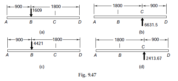
(i) Deflection due to a force of 1609 N [Fig. 9.47(a), Eq. (27) of Table 9.4]:

\tau=\frac{2 M_{t}}{d b l}             (9.27).

\left(\delta_{B}\right)_{1}=\frac{P b x\left(x^{2}+b^{2}-l^{2}\right)}{6 E I l} .

=\frac{(1609)(1800)(900)\left(900^{2}+1800^{2}-2700^{2}\right)}{6 E I(2700)} .

=-\frac{5.2131 \times 10^{11}}{E I} mm               (i).

(ii) Deflection due to a force of 6631.5 N [Fig. 9.47(b), Eq. (27) of Table 9.4]:

\tau=\frac{2 M_{t}}{d b l}             (9.27).

\left(\delta_{B}\right)_{2}=\frac{P b x\left(x^{2}+b^{2}-l^{2}\right)}{6 E I l} .

=\frac{(-6631.5)(900)(900)\left(900^{2}+900^{2}-2700^{2}\right)}{6 E I(2700)} .

=+\frac{18.8 \times 10^{11}}{E I} mm           (ii).

The vertical deflection at B denoted by \left(\delta_{B}\right)_{v} is given by the principle of superimposition.

\left(\delta_{B}\right)_{v}=\left(\delta_{B}\right)_{1}+\left(\delta_{B}\right)_{2} .

=-\frac{5.2131 \times 10^{11}}{E I}+\frac{18.8 \times 10^{11}}{E I} .

=\frac{13.5869 \times 10^{11}}{E I} mm             (a).

Horizontal plane
(i) Deflection due to a force of 4421 N [Fig. 9.47(c), Eq. (27) of Table 9.4]:

\tau=\frac{2 M_{t}}{d b l}             (9.27).

\left(\delta_{B}\right)_{1}=\frac{P b x\left(x^{2}+b^{2}-l^{2}\right)}{6 E I l} .

=\frac{(4421)(1800)(900)\left(900^{2}+1800^{2}-2700^{2}\right)}{6 E I(2700)} .

=-\frac{14.324 \times 10^{11}}{E I} mm           (iii).

(ii) Deflection due to a force of 2413.67 N [Fig. 9.47 (d), Eq. (27) of Table 9.4]:

\tau=\frac{2 M_{t}}{d b l}             (9.27).

\left(\delta_{B}\right)_{2}=\frac{P b x\left(x^{2}+b^{2}-l^{2}\right)}{6 E I l} .

=\frac{(-2413.67)(900)(900)\left(900^{2}+900^{2}-2700^{2}\right)}{6 E I(2700)} .

=+\frac{6.8427 \times 10^{11}}{E I} mm         (iv)

By the principle of superimposition,

\left(\delta_{B}\right)_{h}=\left(\delta_{B}\right)_{1}+\left(\delta_{B}\right)_{2} .

=-\frac{14.324 \times 10^{11}}{E I}+\frac{6.8427 \times 10^{11}}{E I} .

=-\frac{7.4813 \times 10^{11}}{E I} mm             (b).

The radial deflection at the gear B consists of two components—vertical deflection \left(\delta_{B}\right)_{v} and horizontal component \left(\delta_{B}\right)_{h} . The radial deflection \left(\delta_{B}\right)  is given by,

\delta_{B}=\sqrt{\left[\left(\delta_{B}\right)_{v}\right]^{2}+\left[\left(\delta_{B}\right)_{h}\right]^{2}} .

=\sqrt{(13.5869)^{2}+(7.4813)^{2}\left(\frac{10^{11}}{E I}\right)} .

=\frac{15.51 \times 10^{11}}{E I} mm              (c).

Step II Deflection at Gear-C
A similar procedure is used to calculate the deflection at C. The final values of vertical and horizontal deflections are as follows:

\left(\delta_{C}\right)_{v}=+\frac{16.9245 \times 10^{11}}{E I} mm .

\left(\delta_{C}\right)_{h}=-\frac{4.7128 \times 10^{11}}{E I} mm .

\delta_{C}=-\frac{17.5684 \times 10^{11}}{E I} mm            (d).

Step III Shaft diameter
From (c) and (d), the radial deflection is maximum at the gear C. Equating it with permissible deflection,

1=\frac{17.5684 \times 10^{11}}{(207000)\left(\pi d^{4} / 64\right)} .

d = 114.67 mm
In Example 9.4, the shaft diameter was calculated as 68.59 mm on the basis of strength, while in this problem the same has been calculated as 114.67 mm on the basis of rigidity. Therefore, rigidity becomes the criterion of design in this case.

9.6
9.47

Related Answered Questions