Considering the light assembly operation shown in Figure 9.6, what space requirements should be considered for atmosphere systems?
Share
Share
Question 9.1: Considering the light assembly operation shown in Figure 9.6...

The Blue Check Mark means that this solution has been answered and checked by an expert. This guarantees that the final answer is accurate.
Learn more on how we answer questions.
Learn more on how we answer questions.
First, allocate the mechanical equipment room space. Then
- Calculate total gross area: 240^{\prime} \times 120^{\prime}=28,800^{\prime}. From Table 9.2, using office/industrial use type, assume 5 \% of gross area for mechanical equipment space.
- Assume the system will be roof mounted.
| Table 9.2 Central Equipment Room Area by Use | |
| Use | Area of Equipment Rooms |
| Residential | 2% |
| Office/industrial | 5–7% |
| Public assembly | 10–15% |
| Hospital | 25% |
| Laboratory | 25–50% |
| Animal laboratory | 50% |
Second, determine the air handling requirements:
- Minimum air supply rate: 0.6 \mathrm{ft}^{3} / \mathrm{min}-\mathrm{ft}^{2}
Maximum air supply rate: 1.0 \mathrm{ft}^{3} / \mathrm{min}-\mathrm{ft}^{2}
Exhaust 0.3 \mathrm{ft}^{3} / min- \mathrm{ft}^{2}
- Air supply: 28,800 \mathrm{ft}^{2} \times 1.0 \mathrm{ft}^{3} / \mathrm{min}-\mathrm{ft}^{2}=28,800 \mathrm{ft}^{3} / \mathrm{min}(\mathrm{CFM})
Air exhaust: 28,800 \mathrm{ft}^{2} \times 0.3 \mathrm{ft}^{3} / \min -\mathrm{ft}^{2}=8640 \mathrm{ft}^{3} / \mathrm{min}(\mathrm{CFM})
- Determine louver cross-section using respective CFM requirements and allowable air speeds:
\frac{\text { Exhaust: } 8640 \mathrm{ft}^{3} / \mathrm{min}}{2000 \mathrm{ft} / \mathrm{min}}=4.3 \mathrm{ft}^{2}
Note supply and exhaust louvers must be 15^{\prime} apart to avoid “short circuit” of exhaust air back into building.
- Main duct calculation and layout.
Main duct sizing is determined as follows:
Two main ducts, each covering half of the building’s area, multiplied by the air supply rate:
0.5 \times 28,800 \mathrm{ft}^{2} \times 1 \mathrm{ft}^{3} / \min -\mathrm{ft}^{2}=14,400 \mathrm{ft}^{3} / \min CFM. See Figure 9.7 .
Divide this airflow rate by the main duct air speed to obtain the cross-sectional area:
\frac{14,400 \mathrm{CFM}}{1800 \mathrm{ft} / \mathrm{min}}=8 \mathrm{ft}^{2}Main duct can be 2^{\prime} \times 4^{\prime} . See Figure 9.8.
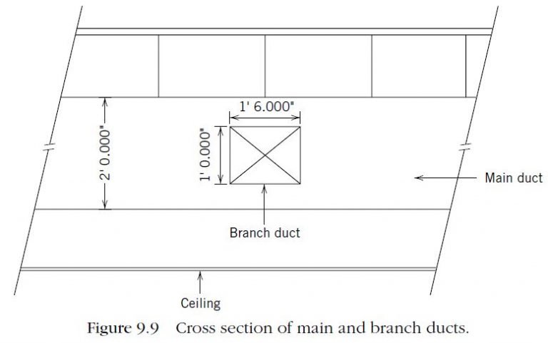
- Branch duct calculation and layout. For each main duct, assume 10 branch ducts. Divide flow rate for each branch duct by the number of branches to obtain the branch flow rate:
Divide the branch flow rate by the allowable branch duct air speed.
\frac{1440 \mathrm{ft}^{3} / \mathrm{min}}{1000 \mathrm{ft} / \mathrm{min}}=1.4 \mathrm{ft}^{2}For the example problem, two main ducts 2^{\prime} 0^{\prime \prime} by 4^{\prime} 0^{\prime \prime} with ten 1^{\prime} 4^{\prime \prime} by 1^{\prime} 0^{\prime \prime} branch ducts wOuld provide the required air dilution to meet the air handling needs (Figure 9.9).
Although the air dilution method is prevalent and widely accepted, it has some drawbacks. The major drawback to this method is that when you exhaust the air, you are removing heat and/or air conditioning. Therefore, there is a substantial loss of energy.
To reduce the volume of makeup air required, many operations use mechanical filtration or electrostatic precipitation. Mechanical filtration removes contaminants by passing air through filtering material, sometimes called media or impingement filters, to remove particulate matter. Electrostatic precipitation removes particulates by charging the air particles and collecting them on oppositely charged plates. The air passes through a prefilter and then into the ionizer section of the unit. Here the particles receive a positive charge. These positively charged particles are then attracted to and collected on high-voltage, negatively charged collecting plates. The cleaner air is then returned to the area.
| Class | Maximum Particles/m^{3} | FED STD 209E Equivalent |
|||||
| 0.1 μm | 0.2 μm | 0.3 μm | 0.5 μm | 1 μm | 5 μm | ||
| ISO 1 | 10 | 2 | |||||
| ISO 2 | 100 | 24 | 10 | 4 | |||
| ISO 3 | 1000 | 237 | 102 | 35 | 8 | Class 1 | |
| ISO 4 | 10,000 | 2370 | 1020 | 352 | 83 | Class 10 | |
| ISO 5 | 100,000 | 23,700 | 10,200 | 3,520 | 832 | 29 | Class 100 |
| ISO 6 | 1,000,000 | 237,000 | 102,000 | 35,200 | 8,320 | 293 | Class 1000 |
| ISO 7 | 352,000 | 83,200 | 2930 | Class 10,000 | |||
| ISO 8 | 3,520,000 | 832,000 | 29,300 | Class 100,000 | |||
| ISO 9 | 35,200,000 | 8,320,000 | 293,000 | Room air | |||


Related Answered Questions
For the building shown in Figure 9.12[/late...
Table 9.15 Plumbing Fixture Requirements for the E...
Using Equation 9.4 results in the following coolin...
Step 1: Determine the level of illumination. From ...
Steps 1 and 2. The same as Example 9.4.
Step 3. Ac...
The following data needed to calculate the heat lo...