Design a 4:1 spur-gear reduction for a 100-hp, three-phase squirrel-cage induction motor running at 1120 rev/min. The load is smooth, providing a reliability of 0.95 at 10^{9} revolutions of the pinion. Gearing space is meager. Use Nitralloy 135M, grade 1 material to keep the gear size small. The gears are heat-treated first then nitrided.
Share
Share
Question 14.8: Design a 4:1 spur-gear reduction for a 100-hp, three-phase s...
The Blue Check Mark means that this solution has been answered and checked by an expert. This guarantees that the final answer is accurate.
Learn more on how we answer questions.
Learn more on how we answer questions.
Make the a priori decisions:
Function: 100 hp, 1120 rev/min, R=0.95, N=10^{9} \text { cycles, } K_{o}=1
• Design factor for unquantifiable exingencies: n_{d}=2
• Tooth system: \phi_{n}=20^{\circ}
• Tooth count: N_{P}=18 \text { teeth, } N_{G}=72 teeth (no interference)
• Quality number: Q_{v}=6, use grade 1 material
• Assume m_{B} \geq 1.2 \text { in Eq. (14-40), } K_{B}=1
Pitch: Select a trial diametral pitch of P_{d}=4 teeth/in. Thus, d_{p}=18 / 4=4.5 in and d_{G}=72 / 4=18 in. From Table 14–2, Y_{P}=0.309, Y_{G}=0.4324 (interpolated). From Fig. 14–6, J_{P}=0.32, J_{G}=0.415
| Table 14–2 Values of the Lewis Form Factor Y (TheseValues Are for a Normal Pressure Angle of 20°, Full-Depth Teeth, and a Diametral Pitch of Unity in the Plane of Rotation) | |||
| Number of Teeth | Y | Number of Teeth | Y |
| 12 | 0.245 | 28 | 0.353 |
| 13 | 0.261 | 30 | 0.359 |
| 14 | 0.277 | 34 | 0.371 |
| 15 | 0.29 | 38 | 0.384 |
| 16 | 0.296 | 43 | 0.397 |
| 17 | 0.303 | 50 | 0.409 |
| 18 | 0.309 | 60 | 0.422 |
| 19 | 0.314 | 75 | 0.435 |
| 20 | 0.322 | 100 | 0.447 |
| 21 | 0.328 | 150 | 0.46 |
| 22 | 0.331 | 300 | 0.472 |
| 24 | 0.337 | 400 | 0.48 |
| 26 | 0.346 | Rack | 0.485 |
V=\frac{\pi d_{P} n_{P}}{12}=\frac{\pi(4.5) 1120}{12}=1319 ft / min
W^{t}=\frac{33000 H}{V}=\frac{33000(100)}{1319}=2502 lbf
From Eqs. (14–28) and (14–27),
\begin{array}{l}A=50+56(1-B) \\B=0.25\left(12-Q_{v}\right)^{2 / 3}\end{array} (14–28)
K_{v}=\left\{\begin{array}{ll}\left(\frac{A+\sqrt{V}}{A}\right)^{B} & V \text { in } ft / min \\\left(\frac{A+\sqrt{200 V}}{A}\right)^{B} & V \text { in } m / s\end{array}\right. (14–27)
B=0.25\left(12-Q_{v}\right)^{2 / 3}=0.25(12-6)^{2 / 3}=0.8255
A=50+56(1-0.8255)=59.77
K_{v}=\left(\frac{59.77+\sqrt{1319}}{59.77}\right)^{0.8255}=1.480
From Eq. (14–38), K_{R}=0.658-0.0759 \ln (1-0.95)=0.885. From Fig. 14–14,
K_{R}=\left\{\begin{array}{ll}0.658-0.0759 \ln (1-R) & 0.5<R<0.99 \\0.50-0.109 \ln (1-R) & 0.99 \leq R \leq 0.9999\end{array}\right. (14–38)
\left(Y_{N}\right)_{p}=1.3558\left(10^{9}\right)^{-0.0178}=0.938
\left(Y_{N}\right)_{G}=1.3558\left(10^{9} / 4\right)^{-0.0178}=0.961
From Fig. 14–15,
\left(Z_{N}\right)_{P}=1.4488\left(10^{9}\right)^{-0.023}=0.900
\left(Z_{N}\right)_{G}=1.4488\left(10^{9} / 4\right)^{-0.023}=0.929
From the recommendation after Eq. (14–8), 3p ≤ F ≤ 5p. Try F = 4p = 4π/P = 4π/4 = 3.14 in. From Eq. (a), Sec. 14–10,
\sigma=\frac{K_{v} W^{t}}{F m Y} (14–8)
\sigma=\frac{M}{I / c}=\frac{6 W^{t} l}{F t^{2}} (a)
K_{s}=1.192\left(\frac{F \sqrt{Y}}{P}\right)^{0.0535}=1.192\left(\frac{3.14 \sqrt{0.309}}{4}\right)^{0.0535}=1.140
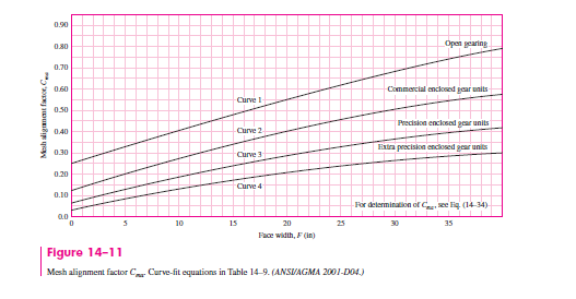
From Eqs. (14–31), (14–33) and (14–35), C_{m c}=C_{p m}=C_{e}=1. From Fig. 14–11, C_{m a}=0.175 for commercial enclosed gear units. From Eq. (14–32), F /\left(10 d_{P}\right)=3.14 / [10(4.5)] = 0.0698. Thus,
C_{m c}=\left\{\begin{array}{ll}1 & \text { for uncrowned teeth } \\0.8 & \text { for crowned teeth }\end{array}\right. (14–31)
C_{p m}=\left\{\begin{array}{ll}1 & \text { for straddle-mounted pinion with } S_{1} / S<0.175 \\1.1 & \text { for straddle-mounted pinion with } S_{1} / S \geq 0.175\end{array}\right. (14–33)
C_{e}=\left\{\begin{array}{cl}0.8 & \text { for gearing adjusted at assembly, or compatibility } \\1 & \text { is improved by lapping, or both } \\\text { for all other conditions }\end{array}\right. (14–35)
C_{p f}=\left\{\begin{array}{ll}\frac{F}{10 d}-0.025 & F \leq 1 \text { in } \\\frac{F}{10 d}-0.0375+0.0125 F & 1<F \leq 17 \text { in } \\\frac{F}{10 d}-0.1109+0.0207 F-0.000228 F^{2} & 17<F \leq 40 \text { in }\end{array}\right. (14–32)
From Eq. (14–30),
K_{m}=C_{m f}=1+C_{m c}\left(C_{p f} C_{p m}+C_{m a} C_{e}\right) (14–30)
K_{m}=1+(1)[0.0715(1)+0.175(1)]=1.247
From Table 14–8, for steel gears, C_{p}=2300 \sqrt{ psi }. From Eq. (14–23), with m_{G}=4 and m_{N}=1
| Table 14–8 Elastic Coefficient C_{p}\left(Z_{E}\right), \sqrt{ psi }(\sqrt{ MPa }) Source: AGMA 218.01 | |||||||
| Gear Material and Modulus of Elasticity E_{G}, lbf / in ^{2}( MPa )^{*} | |||||||
| Pinion Material | Pinion Modulus of \begin{array}{l}\text { Elasticity Ep }\\\text { psi (MPa) * }\end{array} | Steel \begin{array}{l}30 \times 10^{6} \\\left(2 \times 10^{5}\right)\end{array} | Malleable Iron \begin{array}{c}25 \times 10^{6} \\\left(1.7 \times 10^{5}\right)\end{array} | Nodular Iron \begin{array}{c}24 \times 10^{6} \\\left(1.7 \times 10^{5}\right)\end{array} | Cast Iron \begin{array}{r}22 \times 10^{6} \\\left(1.5 \times 10^{5}\right)\end{array} | Aluminum Bronze \begin{array}{r}17.5 \times 10^{6} \\\left(1.2 \times 10^{5}\right)\end{array} | Tin Bronze \begin{array}{c}16 \times 10^{6} \\\left(1.1 \times 10^{5}\right)\end{array} |
| Steel | 30 \times 10^{6} | 2300 | 2180 | 2160 | 2100 | 1950 | 1900 |
| \left(2 \times 10^{5}\right) | (191) | (181) | (179) | (174) | (162) | (158) | |
| Malleable iron | 25 \times 10^{6} | 2180 | 2090 | 2070 | 2020 | 1900 | 1850 |
| \left(1.7 \times 10^{5}\right) | (181) | (174) | (172) | (168) | (158) | (154) | |
| Nodular iron | 24 \times 10^{6} | 2160 | 2070 | 2050 | 2000 | 1880 | 1830 |
| \left(1.7 \times 10^{5}\right) | (179) | (172) | (170) | (166) | (156) | (152) | |
| Cast iron | 22 \times 10^{6} | 2100 | 2020 | 2000 | 1960 | 1850 | 1800 |
| \left(1.5 \times 10^{5}\right) | (174) | (168) | (166) | (163) | (154) | (149) | |
| Aluminum bronze | 17.5 \times 10^{6} | 1950 | 1900 | 1880 | 1850 | 1750 | 1700 |
| \left(1.2 \times 10^{5}\right) | (162) | (158) | (156) | (154) | (145) | (141) | |
| Tin bronze | 16 \times 10^{6} | 1900 | 1850 | 1830 | 1800 | 1700 | 1650 |
| \left(1.1 \times 10^{5}\right) | (158) | (154) | (152) | (149) | (141) | (137) | |
I=\left\{\begin{array}{ll}\frac{\cos \phi_{t} \sin \phi_{t}}{2 m_{N}} \frac{m_{G}}{m_{G}+1} & \text { external gears } \\\frac{\cos \phi_{t} \sin \phi_{t}}{2 m_{N}} \frac{m_{G}}{m_{G}-1} & \text { internal gears }\end{array}\right. (14–23)
I=\frac{\cos 20^{\circ} \sin 20^{\circ}}{2} \frac{4}{4+1}=0.1286
Pinion tooth bending. With the above estimates of K_{s} \text { and } K_{m} from the trial diametral pitch, we check to see if the mesh width F is controlled by bending or wear considerations. Equating Eqs. (14–15) and (14–17), substituting n_{d} W^{t} \text { for } W^{t} , and solving for the face width (F)_{\text {bend }} necessary to resist bending fatigue, we obtain
\sigma=\left\{\begin{array}{ll}W^{t} K_{o} K_{v} K_{s} \frac{P_{d}}{F} \frac{K_{m} K_{B}}{J} & \text { (U.S. customary units) } \\W^{t} K_{o} K_{v} K_{s} \frac{1}{b m_{t}} \frac{K_{H} K_{B}}{Y_{J}} & \text { (SI units) }\end{array}\right. (14–15)
\sigma_{\text {all }}=\left\{\begin{array}{ll}\frac{S_{t}}{S_{F}} \frac{Y_{N}}{K_{T} K_{R}} & \text { (U.S. customary units) } \\\frac{S_{t}}{S_{F}} \frac{Y_{N}}{Y_{\theta} Y_{Z}} & \text { (SI units) }\end{array}\right. (14–17)
(F)_{\text {bend }}=n_{d} W^{t} K_{o} K_{v} K_{s} P_{d} \frac{K_{m} K_{B}}{J_{P}} \frac{K_{T} K_{R}}{S_{t} Y_{N}} (1)
Equating Eqs. (14–16) and (14–18), substituting n_{d} W^{t} \text { for } W^{t}, and solving for the face width (F)_{\text {wear }} necessary to resist wear fatigue, we obtain
\sigma_{c}=\left\{\begin{array}{ll}C_{p} \sqrt{W^{t} K_{o} K_{v} K_{s} \frac{K_{m}}{d_{P} F} \frac{C_{f}}{I}} & \text { (U.S. customary units) } \\Z_{E} \sqrt{W^{t} K_{o} K_{v} K_{s} \frac{K_{H}}{d_{w 1} b} \frac{Z_{R}}{Z_{I}}} & \text { (SI units) }\end{array}\right. (14–16)
\sigma_{c, \text { all }}=\left\{\begin{array}{ll}\frac{S_{c}}{S_{H}} \frac{Z_{N} C_{H}}{K_{T} K_{R}} & \text { (U.S. customary units) } \\\frac{S_{c}}{S_{H}} \frac{Z_{N} Z_{W}}{Y_{\theta} Y_{Z}} & \text { (SI units) }\end{array}\right. (14–18)
(F)_{\text {wear }}=\left(\frac{C_{p} Z_{N}}{S_{c} K_{T} K_{R}}\right)^{2} n_{d} W^{t} K_{o} K_{v} K_{s} \frac{K_{m} C_{f}}{d_{P} I} (2)
From Table 14–5 the hardness range of Nitralloy 135M is Rockwell C32–36 (302–335 Brinell). Choosing a midrange hardness as attainable, using 320 Brinell. From Fig. 14–4,
| Table 14–5 Nominal Temperature Used in Nitriding and Hardnesses Obtained Source: Darle W. Dudley, Handbook of Practical Gear Design, rev. ed., McGraw-Hill, New York, 1984. | ||||
| Steel | Temperature Before Nitriding, °F | Nitriding, °F | Hardness, Rockwell C Scale | |
| Case | Core | |||
| \text { Nitralloy } 135^{*} | 1150 | 975 | 62–65 | 30–35 |
| Nitralloy 135M | 1150 | 975 | 62–65 | 32–36 |
| Nitralloy N | 1000 | 975 | 62–65 | 40–44 |
| AISI 4340 | 1100 | 975 | 48–53 | 27–35 |
| AISI 4140 | 1100 | 975 | 49–54 | 27–35 |
| 31 Cr Mo V 9 | 1100 | 975 | 58–62 | 27–33 |
S_{t}=86.2(320)+12730=40310 psi
Inserting the numerical value of S_{t} in Eq. (1) to estimate the face width gives
(F)_{\text {bend }}=2(2502)(1) 1.48(1.14) 4 \frac{1.247(1)(1) 0.885}{0.32(40310) 0.938}=3.08 \text { in }
From Table 14–6 for Nitralloy 135M, S_{c}=170000 psi. Inserting this in Eq. (2), we find
| Table 14–6 Repeatedly Applied Contact Strength S_{c} \text { at } 10^{7} Cycles and 0.99 Reliability for Steel Gears Source: ANSI/AGMA 2001-D04. | |||||
| Material Designation | Heat Treatment | Minimum Surface \text { Hardness } 1 | Allowable Contact Stress \text { Number, }^{2}{ }^{\prime} S_{c}, \text { psi } | ||
| Grade 1 | Grade 2 | Grade 3 | |||
| \text { Steel }^{3} | Through \text { hardened }{ }^{4} | See Fig. 14–5 | See Fig. 14–5 | See Fig. 14–5 | — |
| \text { Flame }^{5} or induction | 50 HRC | 170 000 | 190 000 | — | |
| \text { hardened }^{5} | 54 HRC | 175 000 | 195 000 | — | |
| Carburized and \text { hardened }^{5} | \text { See Table } 9^{*} | 180 000 | 225 000 | 275 000 | |
| \text { Nitrided }^{5} (through | 83.5 HR15N | 150 000 | 163 000 | 175 000 | |
| hardened steels) | 84.5 HR15N | 155 000 | 168 000 | 180 000 | |
| 2.5% chrome (no aluminum) | \text { Nitrided }^{5} | 87.5 HR15N | 155 000 | 172 000 | 189 000 |
| Nitralloy 135M | \text { Nitrided }^{5} | 90.0 HR15N | 170 000 | 183 000 | 195 000 |
| Nitralloy N | \text { Nitrided }^{5} | 90.0 HR15N | 172 000 | 188 000 | 205 000 |
| 2.5% chrome (no aluminum) | \text { Nitrided }^{5} | 90.0 HR15N | 176 000 | 196 000 | 216 000 |
Notes: See ANSI/AGMA 2001-D04 for references cited in notes 1–5.
{ }^{1} \text { Hardness } to be equivalent to that at the start of active profile in the center of the face width.
{ }^{2} \text { See } Tables 7 through 10 for major metallurgical factors for each stress grade of steel gears.
{ }^{3} \text { The } steel selected must be compatible with the heat treatment process selected and hardness required.
{ }^{4} \text { These } materials must be annealed or normalized as a minimum.
{ }^{5} \text { The } allowable stress numbers indicated may be used with the case depths prescribed in 16.1.
*Table 9 of ANSI/AGMA 2001-D04 is a comprehensive tabulation of the major metallurgical factors affecting S_{t} \text { and } S_{c} of carburized and hardened steel gears.
(F)_{\text {wear }}=\left(\frac{2300(0.900)}{170000(1) 0.885}\right)^{2} 2(2502) 1(1.48) 1.14 \frac{1.247(1)}{4.5(0.1286)}=3.44 \text { in }
Make face width 3.50 in. Correct K_{s} \text { and } K_{m}:
K_{s}=1.192\left(\frac{3.50 \sqrt{0.309}}{4}\right)^{0.0535}=1.147
\frac{F}{10 d_{p}}=\frac{3.50}{10(4.5)}=0.0778
C_{p f}=0.0778-0.0375+0.0125(3.50)=0.0841
K_{m}=1+(1)[0.0841(1)+0.175(1)]=1.259
The bending stress induced by W^{t} in bending, from Eq. (14–15), is
(\sigma)_{P}=2502(1) 1.48(1.147) \frac{4}{3.50} \frac{1.259(1)}{0.32}=19100 psi
The AGMA factor of safety in bending of the pinion, from Eq. (14–41), is
S_{F}=\frac{S_{t} Y_{N} /\left(K_{T} K_{R}\right)}{\sigma}=\frac{\text { fully corrected bending strength }}{\text { bending stress }} (14–41)
\left(S_{F}\right)_{P}=\frac{40310(0.938) /[1(0.885)]}{19100}=2.24
Gear tooth bending. Use cast gear blank because of the 18-in pitch diameter. Use the same material, heat treatment, and nitriding. The load-induced bending stress is in the ratio of J_{P} / J_{G}. Then
(\sigma)_{G}=19100 \frac{0.32}{0.415}=14730 psi
The factor of safety of the gear in bending is
\left(S_{F}\right)_{G}=\frac{40310(0.961) /[1(0.885)]}{14730}=2.97
Pinion tooth wear. The contact stress, given by Eq. (14–16), is
\left(\sigma_{c}\right)_{P}=2300\left[2502(1) 1.48(1.147) \frac{1.259}{4.5(3.5)} \frac{1}{0.129}\right]^{1 / 2}=118000 psi
The factor of safety from Eq. (14–42), is
S_{H}=\frac{S_{c} Z_{N} C_{H} /\left(K_{T} K_{R}\right)}{\sigma_{c}}=\frac{\text { fully corrected contact strength }}{\text { contact stress }} (14–42)
\left(S_{H}\right)_{P}=\frac{170000(0.900) /[1(0.885)]}{118000}=1.465
By our definition of factor of safety, pinion bending is \left(S_{F}\right)_{P}=2.24, and wear is \left(S_{H}\right)_{P}^{2}=(1.465)^{2}=2.15.
Gear tooth wear. The hardness of the gear and pinion are the same. Thus, from Fig. 14–12, C_{H}=1, the contact stress on the gear is the same as the pinion, \left(\sigma_{c}\right)_{G}= 118 000 psi. The wear strength is also the same, S_{c}=170000 psi. The factor of safety of the gear in wear is
\left(S_{H}\right)_{G}=\frac{170000(0.929) /[1(0.885)]}{118000}=1.51
So, for the gear in bending, \left(S_{F}\right)_{G}=2.97, and wear \left(S_{H}\right)_{G}^{2}=(1.51)^{2}=2.29.
Rim. Keep m_{B} \geq 1.2. The whole depth is h_{t}=\text { addendum }+\text { dedendum }=1 / P_{d}+ 1.25 / P_{d}=2.25 / \bar{P}_{d}=2.25 / 4=0.5625 in. The rim thickness t_{R} is
t_{R} \geq m_{B} h_{t}=1.2(0.5625)=0.675 \text { in }
In the design of the gear blank, be sure the rim thickness exceeds 0.675 in; if it does not, review and modify this mesh design.


Related Answered Questions
There will be many terms to obtain so use Figs. 14...
All of the parameters in this example are the same...
For through-hardened grade 1 steel the pinion stre...
From Fig. 14–5,
\left(S_{c}\right)_{...
The term moderate applications seems to imply that...
From Table A–5 we find the elastic constants to be...
The rotating-beam endurance limit is estimated fro...