Design a condenser for the following duty: 45,000 kg/h of mixed light hydrocarbon vapours to be condensed. The condenser to operate at 10 bar. The vapour will enter the condenser saturated at 60^{\circ} C and the condensation will be complete at 45^{\circ} C. The average molecular weight of the vapours is 52. The enthalpy of the vapour is 596.5 kJ/kg and the condensate 247.0 kJ/kg. Cooling water is available at 30^{\circ} C and the temperature rise is to be limited to 10^{\circ} C. Plant standards require tubes of 20 mm o.d., 16.8 mm i.d., 4.88 m (16 ft) long, of admiralty brass. The vapours are to be totally condensed and no sub-cooling is required.
Question 12.7: Design a condenser for the following duty: 45,000 kg/h of mi...
The Blue Check Mark means that this solution has been answered and checked by an expert. This guarantees that the final answer is accurate.
Learn more on how we answer questions.
Learn more on how we answer questions.
Only the thermal design will be done. The physical properties of the mixture will be taken as the mean of those for n-propane (MW = 44) and n-butane (MW = 58), at the average temperature.
\text { Heat transferred from vapour }=\frac{45,000}{3600}(596.5-247.0)=4368.8 kW
\text { Cooling water flow }=\frac{4368.8}{(40-30) 4.18}=104.5 kg / s
\text { Assumed overall coefficient (Table 12.1) }=900 W / m ^{2}{ }^{\circ} C
| Table 12.1. Typical overall coefficients | ||
| Shell and tube exchangers | ||
| Hot fluid | Cold fluid | U\left( W / m ^{2 \circ} C \right) |
| Heat exchangers | ||
| Water | Water | 800-1500 |
| Organic solvents | Organic solvents | 100-300 |
| Light oils | Light oils | 100-400 |
| Heavy oils | Heavy oils | 50-300 |
| Gases | Gases | 10-50 |
| Coolers | ||
| Organic solvents | Water | 250-750 |
| Light oils | Water | 350-900 |
| Heavy oils | Water | 60-300 |
| Gases | Water | 20-300 |
| Organic solvents | Brine | 150-500 |
| Water | Brine | 600-1200 |
| Gases | Brine | 15-250 |
| Heaters | ||
| Steam | Water | 1500-4000 |
| Steam | Organic solvents | 500-1000 |
| Steam | Light oils | 300-900 |
| Steam | Heavy oils | 60-450 |
| Steam | Gases | 30-300 |
| Dowtherm | Heavy oils | 30-300 |
| Dowtherm | Gases | 50-300 |
| Flue gases | Steam | 20-200 |
| Flue | Hydrocarbon vapours | 30-100 |
| Condensers | ||
| Aqueous vapours | Water | 1000-1500 |
| Organic vapours | Water | 700-1000 |
| Organics (some non-condensables) | Water | 500-700 |
| Vacuum condensers | Water | 200-500 |
| Vaporisers | ||
| Steam | Aqueous solutions | 1000-1500 |
| Steam | Light organics | 900-1200 |
| Steam | Heavy organics | 600-900 |
| Air-cooled exchangers | ||
| Process fluid | ||
| Water | 300-450 | |
| Light organics | 300-700 | |
| Heavy organics | 50-150 | |
| \text { Gases, } 5-10 \text { bar } | 50-100 | |
| 10-30 \text { bar } | 100-300 | |
| Condensing hydrocarbons | 300-600 | |
| Immersed coils | ||
| Coil | Pool | |
| Natural circulation | ||
| Steam | Dilute aqueous solutions | 500-1000 |
| Steam | Light oils | 200-300 |
| Steam | Heavy oils | 70-150 |
| Water | Aqueous solutions | 200-500 |
| Water | Light oils | 100-150 |
| Table 12.1. (continued) | ||
| Immersed coils | ||
| Coil | Pool | U\left( W / m ^{2}{ }^{\circ} C \right) |
| Agitated | ||
| Steam | Dilute aqueous solutions | 800-1500 |
| Steam | Light oils | 300-500 |
| Steam | Heavy oils 200 400 | 200-400 |
| Water | Aqueous solutions | 400-700 |
| Water | Light oils | 200-300 |
| Jacketed vessels | ||
| Jacket | Vessel | |
| Steam | Dilute aqueous solutions | 500-700 |
| Steam | Light organics | 250-500 |
| Water | Dilute aqueous solutions | 200-500 |
| Water | Light organics | 200-300 |
| Gasketed-plate exchangers | ||
| Hot fluid | Cold fluid | |
| Light organic | Light organic | 2500-5000 |
| Light organic | Viscous organic | 250-500 |
| Viscous organic | Viscous organic | 100-200 |
| Light organic | Process water | 2500-3500 |
| Viscous organic | Process water | 250-500 |
| Light organic | Cooling water | 2000-4500 |
| Viscous organic | Cooling water | 250-450 |
| Condensing steam | Light organic | 2500-3500 |
| Condensing steam | Viscous organic | 250-500 |
| Process water | Process water | 5000-7500 |
| Process water | Cooling water | 5000-7000 |
| Dilute aqueous solutions | Cooling water | 5000-7000 |
| Condensing steam | Process water | 3500-4500 |
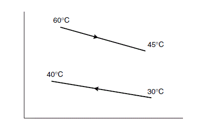
Mean temperature difference: the condensation range is small and the change in saturation temperature will be linear, so the corrected logarithmic mean temperature difference can be used.
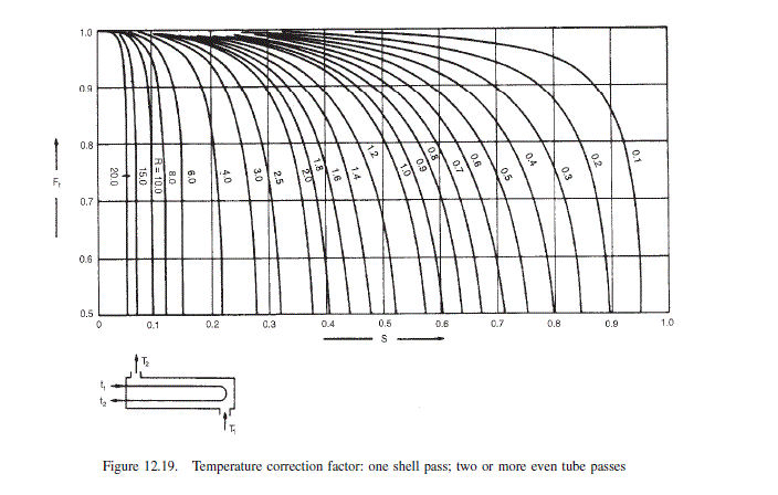
R=\frac{(60-45)}{(40-30)}=1.5 (12.6)
S=\frac{(40-30)}{(60-30)}=0.33 (12.7)
Try a horizontal exchanger, condensation in the shell, four tube passes. For one shell pass, four tube passes, from Figure 12.19, F_{t} = 0.92
\Delta T_{\operatorname{lm}}=\frac{(60-40)-(45-30)}{\ln \frac{(60-40)}{(45-30)}}=17.4^{\circ} C
\Delta T_{m}=0.92 \times 17.4=16^{\circ} C
\text { Trial area }=\frac{4368.8 \times 10^{3}}{900 \times 16}=303 m ^{2}
\text { Surface area of one tube }=20 \times 10^{-3} \pi \times 4.88=0.305 m ^{2} (ignore tube sheet thickness)
\text { Number of tubes }=\frac{303}{0.305}=992
\text { Use square pitch, } P_{t}=1.25 \times 20 mm =25 mm \text {. }
Tube bundle diameter
D_{b}=20\left(\frac{992}{0.158}\right)^{1 / 2.263}=954 mm (12.3b)
\text { Number of tubes in centre row } N_{r}=D_{b} / P_{t}=954 / 25=38
Shell-side coefficient
Estimate tube wall temperature, T_{w}; assume condensing coefficient of 1500 W / m ^{2}{ }^{\circ} C,
Mean temperature
\text { Shell-side }=\frac{60+45}{2}=52.5^{\circ} C
\text { Tube-side }=\frac{40+30}{2}=35^{\circ} C
\begin{aligned}\left(52.5-T_{w}\right) 1500 &=(52.5-35) 900 \\T_{w} &=42.0{ }^{\circ} C\end{aligned}
\text { Mean temperature condensate }=\frac{52.5+42.0}{2}=47^{\circ} C
\text { Physical properties at } 47^{\circ} C
\mu_{L}=0.16 mNs / m ^{2}
\rho_{L}=551 kg / m ^{3}
k_{L}=0.13 W / m ^{\circ} C
vapour density at mean vapour temperature
\rho_{v}=\frac{52}{22.4} \times \frac{273}{(273+52.5)} \times \frac{10}{1}=19.5 kg / m ^{3}
\Gamma_{h}=\frac{W_{c}}{L N_{t}}=\frac{45,000}{3600} \times \frac{1}{4.88 \times 992}=2.6 \times 10^{-3} kg / s m
N_{r}=\frac{2}{3} \times 38=25
\begin{aligned}h_{c} &=0.95 \times 0.13\left[\frac{551(551-19.5) 9.81}{0.16 \times 10^{-3} \times 2.6 \times 10^{-3}}\right]^{1 / 3} \times 25^{-1 / 6} \\&=1375 W / m ^{2{ }^{\circ} C }\end{aligned} (12.50)
\text { Close enough to assumed value of } 1500 W / m ^{2}{ }^{\circ} C \text {, so no correction to } T_{w} \text { needed. }
Tube-side coefficient
\text { Tube cross-sectional area }=\frac{\pi}{4}\left(16.8 \times 10^{-3}\right)^{2} \times \frac{992}{4}=0.055 m ^{2}
\text { Density of water, at } 35^{\circ} C =993 kg / m ^{3}
\text { Tube velocity }=\frac{104.5}{993} \times \frac{1}{0.055}=1.91 m / s
\begin{aligned}h_{i} &=\frac{4200(1.35+0.02 \times 35) 1.91^{0.8}}{16.8^{0.2}} \\&=8218 W / m ^{2 \circ} C\end{aligned} (12.17)
Fouling factors: as neither fluid is heavily fouling, use 6000 W / m ^{2}{ }^{\circ} C for each side.
k_{w}=50 W / m ^{\circ} C
Overall coefficient
\begin{aligned}\frac{1}{U} &=\frac{1}{1375}+\frac{1}{6000}+\frac{20 \times 10^{-3} \ln \left(\frac{20}{16.8}\right)}{2 \times 50}+\frac{20}{16.8} \times \frac{1}{6000}+\frac{20}{16.8} \times \frac{1}{8218} \\U &=786 W / m ^{2}{ }^{\circ} C\end{aligned} (12.2)
\text { Significantly lower than the assumed value of } 900 W / m ^{2}{ }^{\circ} C \text {. }
\text { Repeat calculation using new trial value of } 750 W / m ^{2}{ }^{\circ} C \text {. }
\text { Area }=\frac{4368 \times 10^{3}}{750 \times 16}=364 m ^{2}
\text { Number of tubes }=\frac{364}{0305}=1194
D_{b}=20\left(\frac{1194}{0.158}\right)^{1 / 2.263}=1035 mm (12.36)
\text { Number of tubes in centre row }=\frac{1035}{25}=41
\Gamma_{h}=\frac{45,000}{3600} \times \frac{1}{4.88 \times 1194}=2.15 \times 10^{-3} kg / m s
N_{r}=\frac{2}{3} \times 41=27
\begin{aligned}h_{c} &=0.95 \times 0.13\left[\frac{551(551-19.5) 9.81}{0.16 \times 10^{-3} \times 2.15 \times 10^{-3}}\right]^{1 / 3} \times 27^{-1 / 6} \\&=1447 W / m ^{2}{ }^{\circ} C\end{aligned} (12.50)
\text { New tube velocity }=1.91 \times \frac{992}{1194}=1.59 m / s
h_{i}=4200(1.35+0.02 \times 35) \frac{1.59^{0.8}}{16.8^{0.2}}=7097 W / m ^{2 \circ} C (12.17)
\begin{aligned}\frac{1}{U}=& \frac{1}{1447}+\frac{1}{6000}+\frac{20 \times 10^{-3} \ln \left(\frac{20}{16.8}\right)}{2 \times 50} \\&+\frac{20}{16.8} \times \frac{1}{6000}+\frac{20}{16.8} \times \frac{1}{7097} \\U=& 773 W / m ^{2{ }^{\circ} C }\end{aligned} (12.2)
Close enough to estimate, firm up design.
Shell-side pressure drop
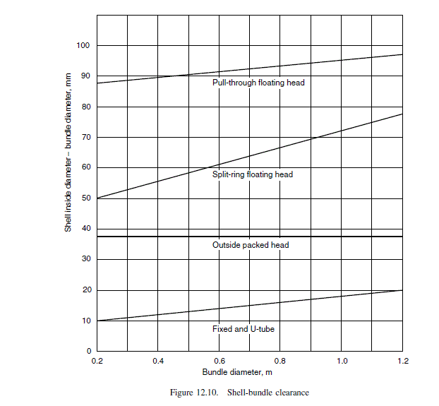
Use pull-through floating head, no need for close clearance.
Select baffle spacing = shell diameter, 45 per cent cut.
From Figure 12.10, clearance = 95 mm.
Shell i.d. = 1035 + 95 = 1130 mm
Use Kern’s method to make an approximate estimate.
\begin{aligned}\text { Cross-flow area } A_{s} &=\frac{(25-20)}{25} 1130 \times 1130 \times 10^{-6} \\&=0.255 m ^{2}\end{aligned} (12.21)
Mass flow-rate, based on inlet conditions
G_{s}=\frac{45,000}{3600} \times \frac{1}{0.255}=49.02 kg / s m ^{2}
\text { Equivalent diameter, } \begin{aligned}d_{e} &=\frac{1.27}{20}\left(25^{2}-0.785 \times 20^{2}\right) \\&=19.8 mm\end{aligned} (12.22)
\text { Vapour viscosity }=0.008 mNs / m ^{2}
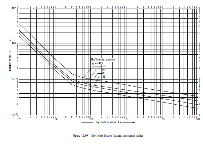
R e=\frac{49.02 \times 19.8 \times 10^{-3}}{0.008 \times 10^{-3}}=121,325
\text { From Figure } 12.30, j_{f}=2.2 \times 10^{-2}
u_{s}=\frac{G_{s}}{\rho_{v}}=\frac{49.02}{19.5}=2.51 m / s
Take pressure drop as 50 per cent of that calculated using the inlet flow; neglect viscosity correction.
\begin{aligned}\Delta P_{s} &=\frac{1}{2}\left[8 \times 2.2 \times 10^{-2}\left(\frac{1130}{19.8}\right)\left(\frac{4.88}{1.130}\right) \frac{19.5(2.51)^{2}}{2}\right] \\&=1322 N / m ^{2} \\&=1.3 kPa\end{aligned} (12.26)
Negligible; more sophisticated method of calculation not justified.
Tube-side pressure drop
\text { Viscosity of water }=0.6 mN s / m ^{2}
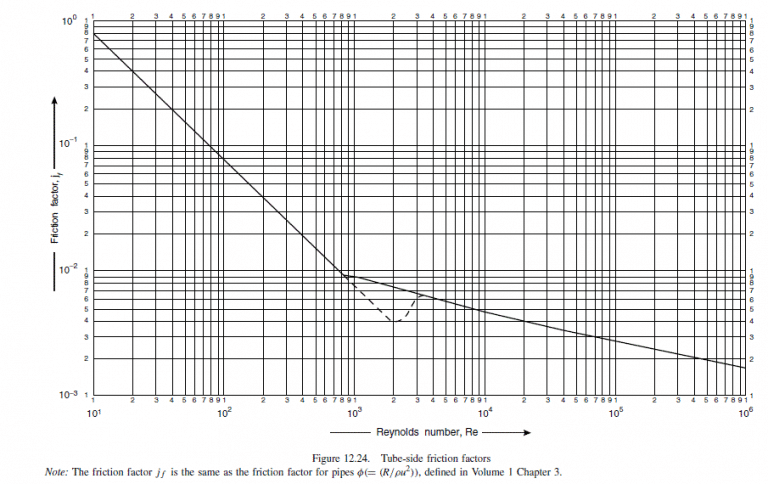
R e=\frac{u_{t} \rho d_{i}}{\mu}=\frac{1.59 \times 993 \times 16.8 \times 10^{-3}}{0.6 \times 10^{-3}}=\underline{\underline{44,208}}
\text { From Figure } 12.24, i_{f}=3.5 \times 10^{-3} \text {. }
Neglect viscosity correction.
\begin{aligned}\Delta P_{t} &=4\left[8 \times 3.5 \times 10^{-3}\left(\frac{4.88}{16.8 \times 10^{-3}}\right)+2.5\right] \frac{993 \times 1.59^{2}}{2} \\&=53,388 N / m ^{2} \\&=53 kPa (7.7 psi ),\end{aligned} (12.20)
acceptable.
Related Answered Questions
Heat-transfer coefficient
\text { Id...
Physical properties, from steam tables:
[la...
The vapour will flow up and the liquid down the tu...
Physical properties:
\text { boiling...
Physical properties, taken as those of aniline:
Bo...
Only the thermal design and general layout will be...
\text { The baffle forms a continuous spira...
The concentrations of C _{3} \text { and } ...
\text { Agitator speed }(\text { revs per s...
NTU, based on the maximum temperature difference
&...