Question 10.4: Design a cyclone to recover solids from a process gas stream...

Design a cyclone to recover solids from a process gas stream. The anticipated particle size distribution in the inlet gas is given below. The density of the particles is 2500 kg / m ^{3}, and the gas is essentially nitrogen at 150^{\circ} C. The stream volumetric flow-rate is 4000 m ^{3} / h, and the operation is at atmospheric pressure. An 80 per cent recovery of the solids is required.

Particle size (\mu m ) 50 40 30 20 10 5 2
Percentage by weight less than 90 75 65 55 30 10 4
The Blue Check Mark means that this solution has been answered and checked by an expert. This guarantees that the final answer is accurate.
Learn more on how we answer questions.

As 30 per cent of the particles are below 10 μm the high-efficiency design will be required to give the specified recovery.


\text { Flow-rate }=\frac{4000}{3600}=1.11 m ^{3} / s


\text { Area of inlet duct, at } 15 m / s =\frac{1.11}{15}=0.07 m ^{2}


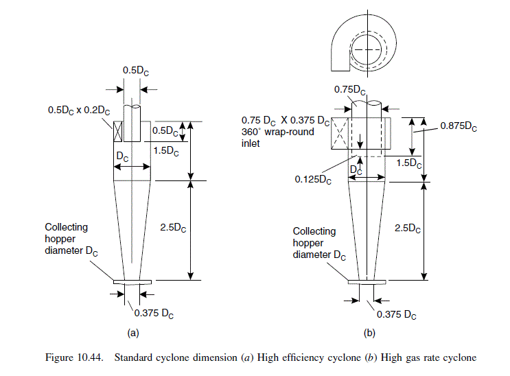
\text { From Figure } 10.44 a \text {, duct area }=0.5 D_{c} \times 0.2 D_{c}


\text { so, } D_{c}=0.84


This is clearly too large compared with the standard design diameter of 0.203 m.


\text { Try four cyclones in parallel, } D_{c}=0.42 m \text {. }


\text { Flow-rate per cyclone }=1000 m ^{3} / h


\text { Density of gas at } 150^{\circ} C =\frac{28}{22.4} \times \frac{273}{423}=0.81 kg / m ^{2} \text {, }


negligible compared with the solids density


\text { Viscosity of } N _{2} \text { at } 150^{\circ} C =0.023 cp \left( mN s / m ^{2}\right)


From equation 10.8,


d_{2}=d_{1}\left[\left(\frac{D_{c_{2}}}{D_{c_{1}}}\right)^{3} \times \frac{Q_{1}}{Q_{2}} \times \frac{\Delta \rho_{1}}{\Delta \rho_{2}} \times \frac{\mu_{2}}{\mu_{1}}\right]^{1 / 2} (10.8)


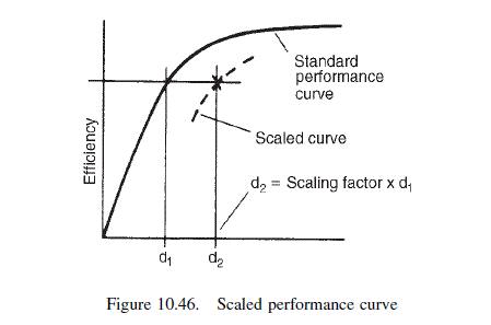
\text { scaling factor }=\left[\left(\frac{0.42}{0.203}\right)^{3} \times \frac{223}{1000} \times \frac{2000}{2500} \times \frac{0.023}{0.018}\right]^{1 / 2}=\underline{\underline{1.42}}


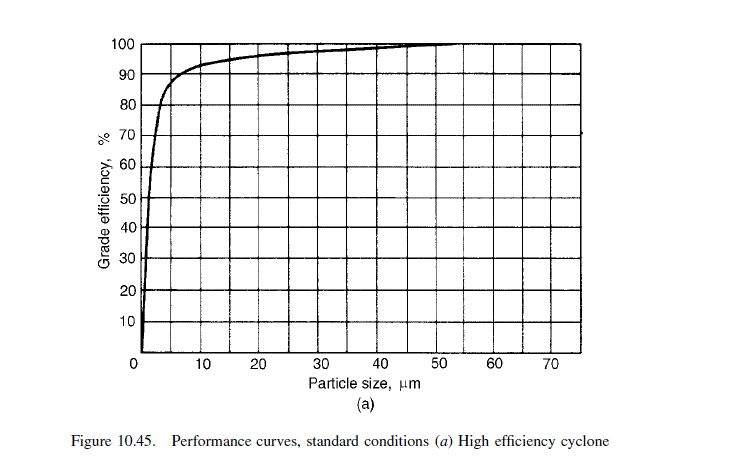
The performance calculations, using this scaling factor and Figure 10.45a, are set out in the table below:


Calculated performance of cyclone design, Example 10.4
1 2 3 4 5 6 7
Particle size (\mu m ) Per cent in range Mean particle size \div \text { scaling } factor Efficiency at scaled size % Figure 10.46a) Collected \frac{(2) \times(4)}{100} Grading at exit (2)- (5) Per cent at exit
>50 10 35 98 9.8 0.2 1.8
50-40 15 32 97 14.6 0.4 3.5
40-30 10 25 96 9.6 0.4 3.5
30-20 10 18 95 9.5 0.5 4.4
20-10 25 11 93 23.3 1.7 15.1
10-5 20 5 86 17.2 2.8 24.8
5-2 6 3 72 4.3 1.7 15.1
2-0 4 1 10 0.4 3.6 31.8
100 Overall collection efficiency 88.7 11.3 100.0


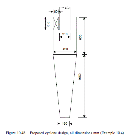
The collection efficiencies shown in column 4 of the table were read from Figure 10.45a at the scaled particle size, column 3. The overall collection efficiency satisfies the specified solids recovery. The proposed design with dimension in the proportions given in Figure 10.44a is shown in Figure 10.48.

Pressure-drop calculation


\text { Area of inlet duct, } A_{1},=210 \times 80=16,800 mm ^{2}


\text { Cyclone surface area, } A_{s}=\pi 420 \times(630+1050) =2.218 \times 10^{6} mm ^{2}


f_{c} \text { taken as } 0.005


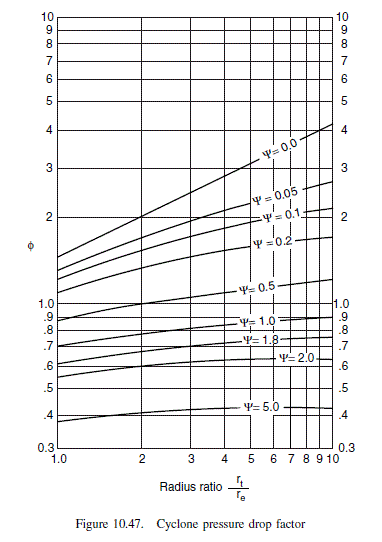
\psi=\frac{f_{c}, A_{s}}{A_{1}}=\frac{0.005 \times 2.218 \times 10^{6}}{16,800}=0.66


\frac{r_{t}}{r_{e}}=\frac{(420-(80 / 2))}{210}=1.81


\text { From Figure } 10.47, \phi=0.9


u_{1}=\frac{1000}{3600} \times \frac{10^{6}}{16,800}=16.5 m / s


\text { Area of exit pipe }=\frac{\pi \times 210^{2}}{4}=34,636 mm ^{2}


u_{2}=\frac{1000}{3600} \times \frac{10^{6}}{34,636}=8.0 m / s


From equation 10.6


u_{c}=\frac{L_{c}}{A_{i}}<u_{d} (10.6)


\Delta P=\frac{0.81}{203}\left[16.5^{2}\left[1+2 \times 0.9^{2}(2 \times 1.81-1)\right]+2 \times 8.0^{2}\right] =\underline{6.4 \text { millibar }}\left(67 mm H { }_{2} O \right)


This pressure drop looks reasonable.

10.4
10.4.
10.4..
10.4...
10.4....

Related Answered Questions