Design a plain surface journal bearing to carry a steady radial load of 1500 lb while the shaft rotates at 850 rpm. The shaft stress analysis determines that the minimum acceptable diameter at the journal is 2.10 in. The shaft is part of a machine requiring good precision.
Share
Share
Question 16.4: Design a plain surface journal bearing to carry a steady rad...
The Blue Check Mark means that this solution has been answered and checked by an expert. This guarantees that the final answer is accurate.
Learn more on how we answer questions.
Learn more on how we answer questions.
Step 1. Let’s select D = 2.50 in. Then R = 1.25 in.
Step 2. For p = 200 psi, L must be
L = F/pD = 1500/(200)(2.50) = 3.00 in
For this value of L, L/D = 3.00/2.50 = 1.20. In order to use one of the standard design charts, let’s change L to 2.50 in so that L/D = 1.0. This is not essential, but it eliminates interpolation. The actual pressure is then
p = F/LD = 1500/(2.50)(2.50) = 240 psi
This is an acceptable pressure.
Step 3. From Figure 16–4, C_d = 0.003 in is suitable for the diametral clearance, based on D = 2.50 in and n = 850 rpm, and C_r = C_d/2 = 0.0015 in. Also,
R/C_r = 1.25/0.0015 = 833
This value is used in later calculations.
Step 4. For the precision desired in this machine, use a surface finish of 16 to 32 min, requiring a ground journal.
Step 5. Minimum film thickness (design value):
h_o = 0.00025D = 0.00025(2.50) = 0.0006 in (approx.)
Step 6. Film thickness variable:
h_o/C_r = 0.0006/0.0015 = 0.40
Step 7. From Figure 16–8, for h_o/C_r = 0.40 and L/D = 1, we can read S = 0.13.
Step 8. Rotational speed in revolutions per second:
n_s = n/60 = 850/60 = 14.2 rev/s
Step 9. Solve for the viscosity from the Sommerfeld number, S:
\mu=\frac{SP}{n_s(R/C_R)^2}=\frac{(0.13)(240)}{(14.2)(833)^2}= 3.17 × 10^{-6} reyn
Step 10. From the viscosity chart, Figure 16–7, SAE 30 oil is required to ensure a sufficient viscosity at 160°F. The actual expected viscosity of SAE 30 at 160°F is approximately 3.3 × 10^{-6} reyn.
Step 11. For the actual viscosity, the Sommerfeld number would be
Step 12. Coefficient of friction variable (from Figure 16–9): f(R/C_r) = 3.5 for S = 0.135 and L/D = 1.
Now, because R/C_r = 833,
f = 3.5/833 = 0.0042
Step 13. Friction torque:
T_f = fFR = (0.0042)(1500)(1.25) = 7.88 lb . in
Step 14. Frictional power:
P_f = T_fn/63 000 = (7.88)(850)/63 000 =0.106 hp
Comment: A qualitative evaluation of the result would require more knowledge about the application. But note that a coefficient of friction of 0.0042 is quite low. It is likely that a machine requiring such a large shaft and with such high bearing forces also requires a large power to drive it. Then the 0.106-hp friction power would appear small.
Thermal considerations are also important to determine how much energy must be dissipated from the bearing. Converting the frictional power loss to thermal power gives
Expressing this in U.S. Customary units gives
P_f=79.0W\frac{1 Btu/h}{0.293 W}= 270 Btu/h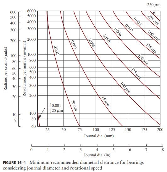


Related Answered Questions
We will use the design procedure previously outlin...
From the given data:
φ = 110°
[late...
We will choose the circular pad design for which t...