Design a vaporiser to vaporise 5000 kg/h n-butane at 5.84 bar. The minimum temperature of the feed (winter conditions) will be 0ŽC. Steam is available at 1.70 bar (10 psig).
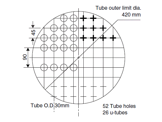
Tube sheet layout, U-tubes, Example 12.9
Design a vaporiser to vaporise 5000 kg/h n-butane at 5.84 bar. The minimum temperature of the feed (winter conditions) will be 0ŽC. Steam is available at 1.70 bar (10 psig).
Tube sheet layout, U-tubes, Example 12.9
Only the thermal design and general layout will be done. Select kettle type.
Physical properties of n-butane at 5.84 bar:
\text { boiling point }=56.1^{\circ} C
latent heat = 326 kJ/kg
\text { mean specific heat, liquid }=2.51 kJ / kg ^{\circ} C
\text { critical pressure, } P_{c}=38 \text { bar }
Heat loads:
\text { sensible heat }(\text { maximum })=(56.1-0) 2.51=140.8 kJ / kg
\text { total heat load }=(140.8+326) \times \frac{5000}{3600}=648.3 kW
add 5 per cent for heat losses
\begin{aligned}\text { maximum heat load }(\text { duty }) &=1.05 \times 648.3 \\&=681 kW\end{aligned}
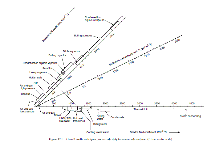
From Figure 12.1 assume U = 1000 W / m ^{2}{ }^{\circ} C \text {. }
Mean temperature difference; both sides isothermal, steam saturation temperature at 1.7 bar = 115.2{ }^{\circ} C
\Delta T_{m}=115.2-56.1=59.1^{\circ} C
\text { Area (outside) required }=\frac{681 \times 10^{3}}{1000 \times 59.1}=11.5 m ^{2}
Select 25 mm i.d., 30 mm o.d. plain U-tubes,
Nominal length 4.8 m (one U-tube)
\text { Number of } U \text { tubes }=\frac{11.5}{\left(30 \times 10^{-3}\right) \pi 4.8}=25
\text { Use square pitch arrangement, pitch }=1.5 \times \text { tube p.d. }
=1.5 \times 30=45 mm
Draw a tube layout diagram, take minimum bend radius
1.5 \times \text { tube o.d. }=45 mm
Proposed layout gives 26 U-tubes, tube outer limit diameter 420 mm.
Boiling coefficient
Use Mostinski’s equation:
heat flux, based on estimated area,
q=\frac{681}{11.5}=59.2 kW / m ^{2}
\begin{aligned}h_{n b} &=0.104(38)^{0.69}\left(59.2 \times 10^{3}\right)^{0.7}\left[1.8\left(\frac{5.84}{38}\right)^{0.17}+4\left(\frac{5.84}{38}\right)^{1.2}+10\left(\frac{5.84}{38}\right)^{10}\right] \\&=4855 W / m ^{2}{ }^{\circ} C\end{aligned} (12.63)
Take steam condensing coefficient as 8000 W / m ^{2}{ }^{\circ} C, fouling coefficient 5000 W / m ^{2}{ }^{\circ} C;
butane fouling coefficient, essentially clean, 10,000 W / m ^{2}{ }^{\circ} C.
Tube material will be plain carbon steel, k_{w}=55 W / m ^{\circ} C
\begin{aligned}\frac{1}{U_{o}} &=\frac{1}{4855}+\frac{1}{10,000}+\frac{30 \times 10^{-3} \ln \frac{30}{25}}{2 \times 55}+\frac{30}{25}\left(\frac{1}{5000}+\frac{1}{8000}\right) \\U_{o} &=1341 W / m ^{2}{ }^{\circ} C\end{aligned} (12.2)
Close enough to original estimate of 1000 W / m ^{2}{ }^{\circ} C for the design to stand.
Myers and Katz (Chem. Eng. Prog. Sym. Ser. 49(5) 107 114) give some data on the boiling of n-butane on banks of tubes. To compare the value estimate with their values an estimate of the boiling film temperature difference is required:
=\frac{1341}{4855} \times 59.1=16.3^{\circ} C
Myers data, extrapolated, gives a coefficient of around 3000 Btu/h ft ^{2} F \text { at } a 29^{\circ} F temperature difference = 17,100 W / m ^{2}{ }^{\circ} C, so the estimated value of 4855 is certainly on the safe side.
Check maximum allowable heat flux. Use modified Zuber equation.
\text { Surface tension }(\text { estimated })=9.7 \times 10^{-3} N / m
\rho_{L}=550 kg / m ^{3}
\rho_{v}=\frac{58}{22.4} \times \frac{273}{(273+56)} \times 5.84=12.6 kg / m ^{3}
N_{t}=52
\text { For square arrangement } K_{b}=0.44
\begin{aligned}q_{c} &=0.44 \times 1.5 \times \frac{326 \times 10^{3}}{\sqrt{52}}\left[9.7 \times 10^{-3} \times 9.81(550-12.6) 12.6^{2}\right]^{0.25} \\&=283,224 W / m ^{2} \\&=280 kW / m ^{2}\end{aligned} (12.74)
Applying a factor of 0.7, maximum flux should not exceed 280 x 0.7 = 196 kW / m ^{2}.
Actual flux of 59.2 kW / m ^{2} is well below maximum allowable.
Layout
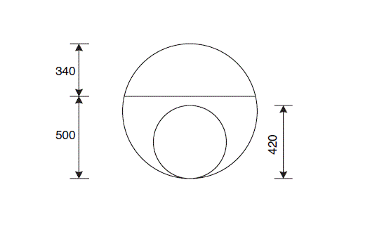
\text { From tube sheet layout } D_{b}=420 mm \text {. }
Take shell diameter as twice bundle diameter
D_{s}=2 \times 420=840 mm .
Take liquid level as 500 mm from base,
freeboard = 840 – 500 = 340 mm, satisfactory.
From sketch, width at liquid level = 0.8 m.
Surface area of liquid = 0.8 x 2.4 = 1.9 m ^{2}.
\text { Vapour velocity at surface }=\frac{5000}{3600} \times \frac{1}{12.6} \times \frac{1}{1.9}=\underline{\underline{0.06 m / s }}
Maximum allowable velocity
\hat{u}_{v}=0.2\left[\frac{550-12.6}{12.6}\right]^{1 / 2}=\underline{\underline{\underline{1.3} m / s }} (12.75)
so actual velocity is well below maximum allowable velocity. A smaller shell diameter could be considered.


