Determine the bending moment at the point B in the simply supported beam ABC shown in Fig. 4.11(a).
Share
Share
Question 4.5: Determine the bending moment at the point B in the simply su...

The Blue Check Mark means that this solution has been answered and checked by an expert. This guarantees that the final answer is accurate.
Learn more on how we answer questions.
Learn more on how we answer questions.
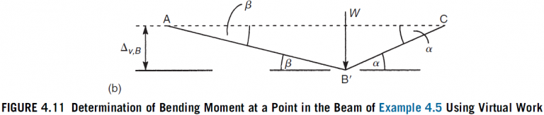
We determined the support reactions for this particular beam in Example 4.4. In this example, however, we are interested in the actual internal moment, M_{ B }, at the point of application of the load. We must therefore impose a virtual displacement that relates the internal moment at B to the applied load and excludes other unknown external forces, such as the support reactions, and unknown internal force systems, such as the bending moment distribution along the length of the beam. Therefore, if we imagine that the beam is hinged at B and that the lengths AB and BC are rigid, a virtual displacement, \Delta_{v, B }, at B results in the displaced shape shown in Fig. 4.11(b). Note that the support reactions at A and C do no work and that the internal moments in AB and BC do no work because AB and BC are rigid links. From Fig. 4.11(b),
\Delta_{v, B }=a \beta=b \alpha (i)
Hence,
\alpha=\frac{a}{b} \beta
and the angle of rotation of BC relative to AB is then
\theta_{ B }=\beta+\alpha=\beta\left(1+\frac{a}{b}\right)=\frac{L}{b} \beta (ii)
Now, equating the external virtual work done by W to the internal virtual work done by M_{ B } (see Eq. (4.23)), we have
W_{e}=W_{i} (4.23)
W \Delta_{v, B }=M_{ B } \theta_{ B } (iii)
Substituting in Eq. (iii) for \Delta_{V, B } from Eq. (i) and for \theta_{ B } from Eq. (ii), we have
W a \beta=M_{ B } \frac{L}{b} \beta
which gives
M_{ B }=\frac{W a b}{L}
which is the result we would have obtained by calculating the moment of R_{ C }(=W a / L from Example 4.4) about B.
Related Answered Questions
The virtual force systems, that is, unit loads, re...
The actual rotation of the beam at A produced by t...
A plan view of the beam is shown in Fig. 4.17. To ...
The horizontal and vertical components of the defl...
We are required to calculate the force in the memb...
Only a vertical load is applied to the beam, so th...
The concentrated load, W, induces a vertical react...
In this case, we obtain a solution by simultaneous...
Let us suppose that the actual deflection of the c...
In this example the load, W, produces reactions of...