Estimate the horsepower rating of the gear in the previous example based on obtaining an infinite life in bending.
The rotating-beam endurance limit is estimated from Eq. (6–8)
S_{e}^{\prime}=\left\{\begin{array}{ll}0.5 S_{u t} & S_{u t} \leq 200 kpsi (1400 MPa ) \\100 kpsi & S_{u t}>200 kpsi \\700 MPa & S_{u t}>1400 MPa\end{array}\right. (6–8)
S_{e}^{\prime}=0.5 S_{u t}=0.5(55)=27.5 kpsi
To obtain the surface finish Marin factor k_{a} we refer to Table 6–3 for machined surface, finding a = 2.70 and b = −0.265. Then Eq. (6–19) gives the surface finish Marin factor k_{a} as
k_{a}=a S_{u t}^{b} (6–19)
k_{a}=a S_{u t}^{b}=2.70(55)^{-0.265}=0.934
| Table 6–3 A_{0.95 \sigma} Areas of Common Nonrotating Structural Shapes | |
 |
\begin{aligned}A_{0.95 \sigma} &=0.01046 d^{2} \\d_{e} &=0.370 d\end{aligned} |
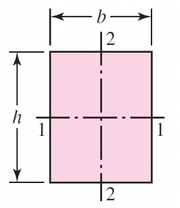 |
\begin{aligned}A_{0.95 \sigma} &=0.05 h b \\d_{e} &=0.808 \sqrt{h b}\end{aligned} |
 |
A_{0.95 \sigma}=\left\{\begin{array}{ll}0.10 at_{f} & &\text { axis } 1-1 \\0.05ba & t_{f}>0.025a&\text { axis } 2-2\end{array}\right. |
 |
A_{0.95 \sigma}=\left\{\begin{array}{ll}0.05 a b & \text { axis } 1-1 \\0.052 x a+0.1 t_{f}(b-x) & \text { axis } 2-2\end{array}\right. |
The next step is to estimate the size factor k_{b}. From Table 13–1, the sum of the addendum and dedendum is
| Table 13–1 Standard and Commonly Used Tooth Systems for Spur Gears | |||
| Tooth System | Pressure Angle \phi, deg | Addendum a | Dedendum b |
| Full depth | 20 | 1 / P_{d} \text { or } 1 m | 1.25 / P_{d} \text { or } 1.25 m |
| 1.35 / P_{d} \text { or } 1.35 m | |||
| 22 \frac{1}{2} | 1 / P_{d} \text { or } 1 m | 1.25 / P_{d} \text { or } 1.25 m | |
| 1.35 / P_{d} \text { or } 1.35 m | |||
| 25 | 1 / P_{d} \text { or } 1 m | 1.25 / P_{d} \text { or } 1.25 m | |
| 1.35 / P_{d} \text { or } 1.35 m | |||
| Stub | 20 | 0.8 / P_{d} \text { or } 0.8 m | 1 / P_{d} \quad \text { or } 1 m |
l=\frac{1}{P}+\frac{1.25}{P}=\frac{1}{8}+\frac{1.25}{8}=0.281 \text { in }
The tooth thickness t in Fig. 14–1b is given in Sec. 14–1 [Eq. (b)] as t=(4 l x)^{1 / 2} when x = 3Y/(2P) from Eq. (14–3). Therefore, since from Ex. 14–1 Y = 0.296 and P = 8,
\frac{t / 2}{x}=\frac{l}{t / 2} \quad \text { or } \quad x=\frac{t^{2}}{4 l} (b)
Y=\frac{2 x P}{3} (14–3)
x=\frac{3 Y}{2 P}=\frac{3(0.296)}{2(8)}=0.0555 \text { in }
then
t=(4 l x)^{1 / 2}=[4(0.281) 0.0555]^{1 / 2}=0.250 \text { in }
We have recognized the tooth as a cantilever beam of rectangular cross section, so the equivalent rotating-beam diameter must be obtained from Eq. (6–25):
d_{e}=0.808(h b)^{1 / 2} (6–25)
d_{e}=0.808(h b)^{1 / 2}=0.808(F t)^{1 / 2}=0.808[1.5(0.250)]^{1 / 2}=0.495 \text { in }
Then, Eq. (6–20) gives k_{b} as
k_{b}=\left\{\begin{array}{ll}(d / 0.3)^{-0.107}=0.879 d^{-0.107} & 0.11 \leq d \leq 2 \text { in } \\0.91 d^{-0.157} & 2<d \leq 10 \text { in } \\(d / 7.62)^{-0.107}=1.24 d^{-0.107} & 2.79 \leq d \leq 51 mm \\1.51 d^{-0.157} & 51<d \leq 254 mm\end{array}\right. ( 6–20)
k_{b}=\left(\frac{d_{e}}{0.30}\right)^{-0.107}=\left(\frac{0.495}{0.30}\right)^{-0.107}=0.948
The load factor k_{c} from Eq. (6–26) is unity. With no information given concerning temperature and reliability we will set k_{d}=k_{e}=1.
In general, a gear tooth is subjected only to one-way bending. Exceptions include idler gears and gears used in reversing mechanisms. We will account for one-way bending by establishing a miscellaneous-effects Marin factor k_{f} .
For one-way bending the steady and alternating stress components are \sigma_{a}=\sigma_{m} = \sigma / 2 \text { where } \sigma is the largest repeatedly applied bending stress as given in Eq. (14–7). If a material exhibited a Goodman failure locus,
k_{c}=\left\{\begin{array}{ll}1 & \text { bending } \\0.85 & \text { axial } \\0.59 & \text { torsion }^{17}\end{array}\right. (6–26)
\sigma=\frac{K_{v} W^{t} P}{F Y} (14–7)
\frac{S_{a}}{S_{e}^{\prime}}+\frac{S_{m}}{S_{u t}}=
Since S_{a} and S_{m} are equal for one-way bending, we substitute S_{a} for S_{m} and solve the preceding equation for S_{a} , giving
S_{a}=\frac{S_{e}^{\prime} S_{u t}}{S_{e}^{\prime}+S_{u t}}
Now replace S_{a} with σ/2, and in the denominator replace S_{e}^{\prime} with 0.5S_{u t} to obtain
\sigma=\frac{2 S_{e}^{\prime} S_{u t}}{0.5 S_{u t}+S_{u t}}=\frac{2 S_{e}^{\prime}}{0.5+1}=1.33 S_{e}^{\prime}
Now k_{f}=\sigma / S_{e}^{\prime}=1.33 S_{e}^{\prime} / S_{e}^{\prime}=1.33. a Gerber fatigue locus gives mean values of
\frac{S_{a}}{S_{e}^{\prime}}+\left(\frac{S_{m}}{S_{u t}}\right)^{2}=1
Setting S_{a}=S_{m} and solving the quadratic in S_{a} gives
S_{a}=\frac{S_{u t}^{2}}{2 S_{e}^{\prime}}\left(-1+\sqrt{1+\frac{4 S_{e}^{\prime 2}}{S_{u t}^{2}}}\right)
Setting S_{a}=\sigma / 2, S_{u t}=S_{e}^{\prime} / 0.5 gives
\sigma=\frac{S_{e}^{\prime}}{0.5^{2}}\left[-1+\sqrt{1+4(0.5)^{2}}\right]=1.66 S_{e}^{\prime}
and k_{f}=\sigma / S_{s}^{\prime}=1.66. Since a Gerber locus runs in and among fatigue data and Goodman does not, we will use k_{f}=1.66. The Marin equation for the fully corrected endurance strength is
\begin{aligned}S_{e} &=k_{a} k_{b} k_{c} k_{d} k_{e} k_{f} S_{e}^{\prime} \\&=0.934(0.948)(1)(1)(1) 1.66(27.5)=40.4 kpsi\end{aligned}
For stress, we will first determine the fatigue stress-concentration factor K_{f}. For a 20◦ full-depth tooth the radius of the root fillet is denoted r_{f}, where
r_{f}=\frac{0.300}{P}=\frac{0.300}{8}=0.0375 \text { in }
From Fig. A–15–6
\frac{r}{d}=\frac{r_{f}}{t}=\frac{0.0375}{0.250}=0.15
Since D/d =∞, we approximate with D/d = 3, giving K_{t}=1.68. From Fig. 6–20, q = 0.62. From Eq. (6–32)
K_{f}=1+q\left(K_{t}-1\right) \quad \text { or } \quad K_{f s}=1+q_{\text {shear }}\left(K_{t s}-1\right) (6–32)
K_{f}=1+(0.62)(1.68-1)=1.42
For a design factor of n_{d}=3, as used in Ex. 14–1, applied to the load or strength, the maximum bending stress is
\sigma_{\max }=K_{f} \sigma_{ all }=\frac{S_{e}}{n_{d}}
\sigma_{\text {all }}=\frac{S_{e}}{K_{f} n_{d}}=\frac{40.4}{1.42(3)}=9.5 kpsi
The transmitted load W^{t} is
W^{t}=\frac{F Y \sigma_{\text {all }}}{K_{v} P}=\frac{1.5(0.296) 9500}{1.52(8)}=347 lbf
and the power is, with V = 628 ft/min from Ex. 14–1,
h p=\frac{W^{t} V}{33000}=\frac{347(628)}{33000}=6.6 hp
Again, it should be emphasized that these results should be accepted only as preliminary estimates to alert you to the nature of bending in gear teeth.

