Rigid bar ABCD is loaded and supported as shown in Figure P5.65. Bar (1) is made of bronze [E = 100 GPa, α = 16.9 × 10^{-6}/°C] and has a cross-sectional area of 400 mm ^{2} . Bar (2) is made of aluminum [E = 70 GPa, α = 22.5 × 10^{-6}/°C] and has a cross-sectional area of 600 mm ^{2} . Bars (1) and (2) are initially unstressed. After the temperature has increased by 40°C, determine:
(a) the stresses in bars (1) and (2).
(b) the vertical deflection of point A.
Share
Share
Question 5.65: Rigid bar ABCD is loaded and supported as shown in Figure P5...

The Blue Check Mark means that this solution has been answered and checked by an expert. This guarantees that the final answer is accurate.
Learn more on how we answer questions.
Learn more on how we answer questions.
Equilibrium
Consider a FBD of the rigid bar. Assume tension forces in members (1) and (2). A moment equation about pin D gives the best information for this situation:
\Sigma M_{D}=(3 m ) F_{1}-(1 m ) F_{2}=0 \quad \therefore F_{2}=3 F_{1} (a)
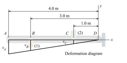
Geometry of Deformations Relationship
Draw a deformation diagram of the rigid bar. The deflections of the rigid bar are related by similar triangles:
\frac{v_{A}}{4 m }=\frac{v_{B}}{3 m }=\frac{v_{C}}{1 m } (b)
There are no gaps, clearances, or other misfits at pins B and C; therefore, Eq. (b) can be rewritten in terms of the member deformations as:
\frac{-\delta_{1}}{3 m }=\frac{\delta_{2}}{1 m } \quad \therefore \delta_{1}=-3 \delta_{2} (c)
Note: To understand the negative sign associated with \delta_{1}, see Section 5.5 for discussion of statically indeterminate rigid bar configurations with opposing members.
Force-Temperature-Deformation Relationships
\delta_{1}=\frac{F_{1} L_{1}}{A_{1} E_{1}}+\alpha_{1} \Delta T_{1} L_{1} \quad \delta_{2}=\frac{F_{2} L_{2}}{A_{2} E_{2}}+\alpha_{2} \Delta T_{2} L_{2} (d)
Compatibility Equation
\frac{F_{1} L_{1}}{A_{1} E_{1}}+\alpha_{1} \Delta T_{1} L_{1}=-3\left[\frac{F_{2} L_{2}}{A_{2} E_{2}}+\alpha_{2} \Delta T_{2} L_{2}\right] (e)
Solve the Equations
For this situation, \Delta T_{1}=\Delta T_{2}=\Delta T=40^{\circ} C . Substitute Eq. (a) into Eq. (e):
and solve for F_{1}:
\begin{aligned}F_{1} &=-\frac{\Delta T\left(3 \alpha_{2} L_{2}+\alpha_{1} L_{1}\right)}{\frac{L_{1}}{A_{1} E_{1}}+\frac{9 L_{2}}{A_{2} E_{2}}} \\&=-\frac{\left(40^{\circ} C \right)\left[3\left(22.5 \times 10^{-6} /{ }^{\circ} C \right)(920 mm )+\left(16.9 \times 10^{-6} /{ }^{\circ} C \right)(840 mm )\right]}{\frac{940 mm }{\left(400 mm ^{2}\right)\left(100,000 N / mm ^{2}\right)}+\frac{9(920 mm )}{\left(600 mm ^{2}\right)\left(70,000 N / mm ^{2}\right)}} \\&=-13,990 N =-13.990 kN\end{aligned}Backsubstitute into Eq. (a) to find F_{2} = −41.970 kN.
(a) Normal Stresses
The normal stresses in each axial member can now be calculated:
(b) Deflection of the rigid bar at A
Calculate the deformation of one of the axial members, say member (1):
Since there are no gaps at pin B, the rigid bar deflection at B is equal to the deformation of member (1);
therefore, v_{B}=\delta_{1}=0.27405 mm \text { (upward). } From similar triangles, the deflection of the rigid bar at A is related to v_{B} by:
The deflection of the rigid bar at A is thus:
v_{A}=\frac{4 m }{3 m } v_{B}=\frac{4 m }{3 m }(0.27405 mm )=0.365 mm \uparrow

Related Answered Questions
Equilibrium
Consider a FBD at joint B. Assume that...
Equilibrium
Consider a FBD at joint B. Assume that...
Equilibrium: Consider a FBD of flange B. Sum force...
Equilibrium
Consider a FBD of the rigid bar. Assum...
Equilibrium
Consider a FBD cut through the assembl...
Equilibrium
Consider a FBD of the rigid bar. Assum...
An incremental length dy of the bar has an increme...
(a) Force at base of pile: Consider the entire pil...
Equilibrium
Consider a FBD of joint D. Assume tens...
Equilibrium: The force induced in the bolt by adva...